2 layers78.7 × 58.4 mm

 Rajcr2/ESLS
This was my academic project focused on creating a efficient LED based Street Lighting System which will avoid Power Wastage due to manual mismanagement.
ESLS is an open-source printed circuit board by Rajcr2, from the Rajcr2/ESLS repository on GitHub, published under the MIT licence. It is a 2-layer board of 90 × 64.5 mm with 11 parts on 40 nets, routed with 71 tracks and 0 vias.
It is built around the BT136-600E, DS1307+ and MOC3021M. Its parts include 5 connectors, 2 resistors, 2 ICs and 1 transistor. It belongs with the AVR (ATmega, ATtiny) boards of this library.


This was my academic project focused on creating a efficient LED based Street Lighting System which will avoid Power Wastage due to manual mismanagement.
I have observed many times that street lights were ON till 10 AM because operator forgot shut the main switch down and seen this very frequently & also lights were ON 1/2 hrs before SUNSET which leads to Power Wastage this is the Main reason or motivation behind this project.
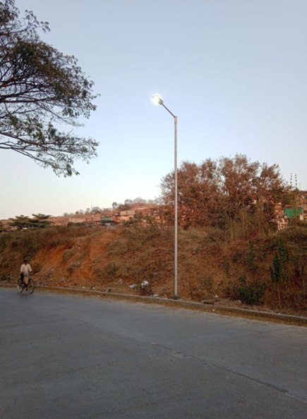
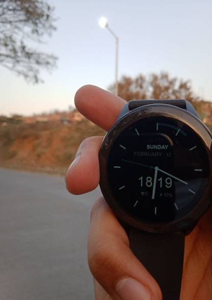
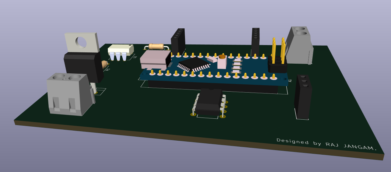
| Component | Purpose |
|---|---|
| Arduino Nano | Microcontroller control unit |
| DS1307 - RTC Module | Time scheduling |
| MOC3021 | Opto-isolated TRIAC driver |
| BT136 - TRIAC | AC load switching |
| LDR Module | Detects ambient light intensity (luminance) |
| 470Ω Resistor | Limits current into optocoupler LED |
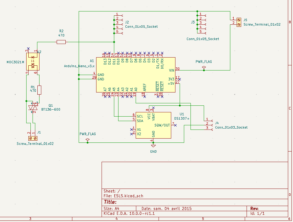
The schematic is designed in KiCad. Schematic consists Arduino Nano (Control Unit), DS1307 RTC Module, optocoupler driver (MOC3021), BT136 TRIAC (switching circuit) for AC load along with Resistors.
The PCB layout separates the low-voltage control circuitry from the AC power section to maintain electrical isolation. Routing was optimized to keep the power path short and reduce noise coupling.
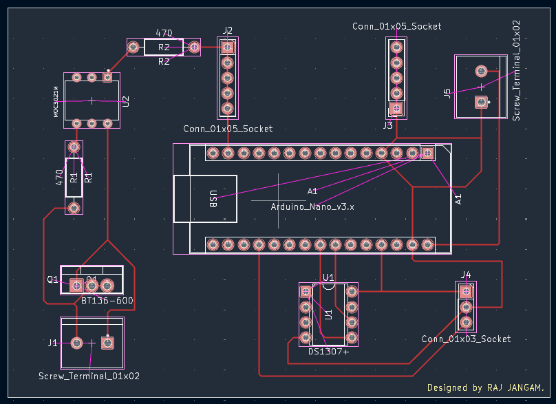
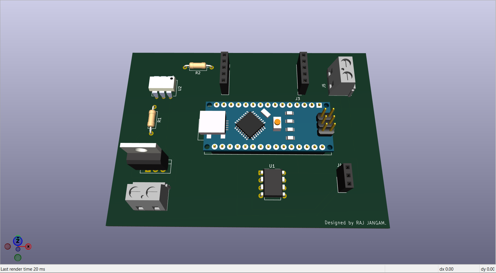
Transient analysis was performed using ngspice integrated in KiCad to validate the Arduino driver stage.
Limitation
Since microcontrollers cannot be simulated directly in SPICE, the Arduino PWM output was emulated using a pulse voltage source.
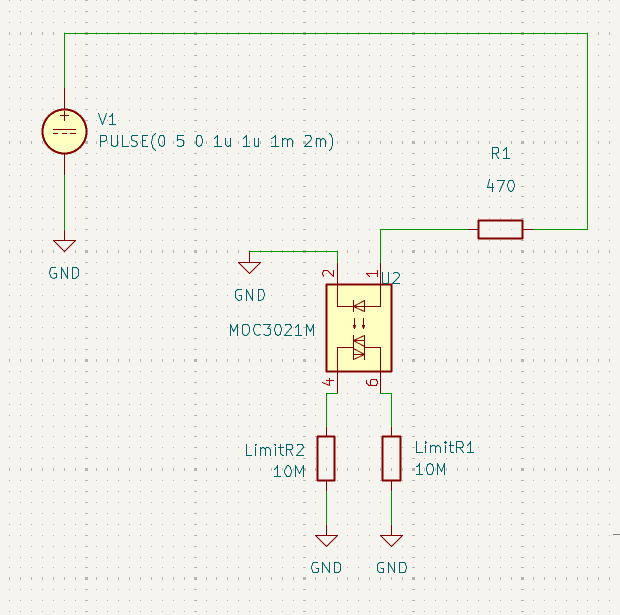
All required Arduino PWM signals were emulated using the SPICE source :
Example : PULSE(0 5 0 1u 1u 1m 2m)
| Parameter | Value |
|---|---|
| Low Voltage | 0 V |
| High Voltage | 5 V |
| Rise Time | 1 µs |
| Fall Time | 1 µs |
| ON Time | 1 ms |
| Period | 2 ms |
This results in a 50% duty cycle PWM signal, which corresponds to the Arduino command:
analogWrite(pin,128)
The transient simulation produced the following waveform.
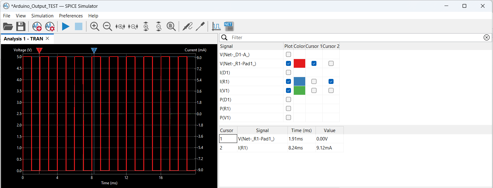
Observations from the simulation :
Calculation :
I = (Vcc − Vf) / R
Vcc = 5 V, Vf ≈ 1.2 V (LED forward voltage), R = 470 Ω
I ≈ (5 − 1.2) / 470
I ≈ 8 mA
To verify the embedded firmware behavior, the system was simulated in Proteus.
Unlike SPICE tools, Proteus allows simulation of Arduino code execution along with peripheral modules such as the RTC.
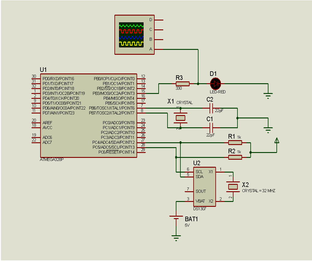
Simulation demonstrates and displays output Oscilloscope how the Arduino program changes the output signal according to the RTC time conditions.
As per our goal light must remain off during Day Time and thats we have achieved. It will only "Turn ON" if LDR triggers due to cloudy condition.
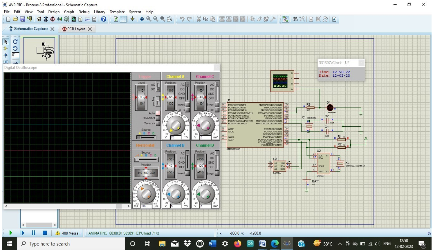
As during sunset time, we need light but, not fully in regular seasons so, 50% light is enough and that we got it. For special case, during cloudy conditions if it senses Darkness around will trigger LDR. so, Both scenarios are covered.
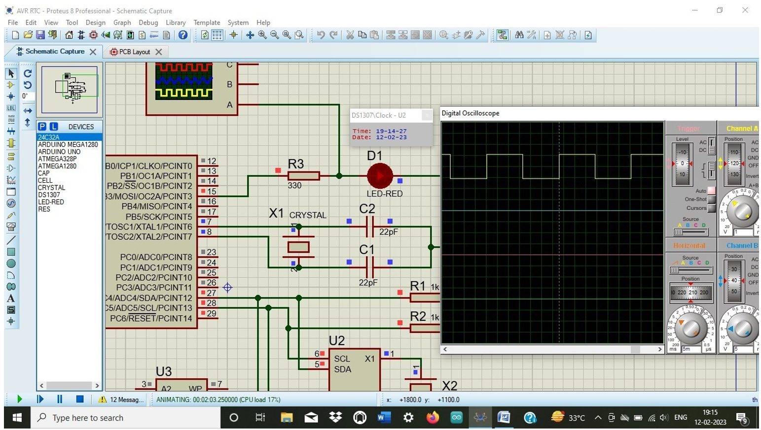
Light is fully ON.
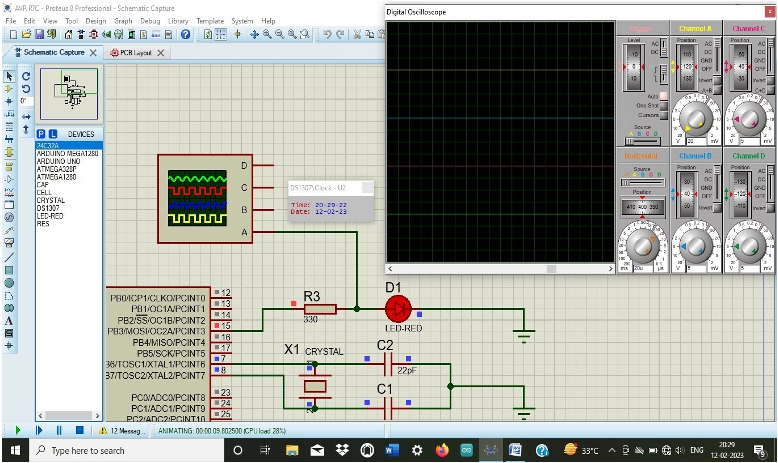
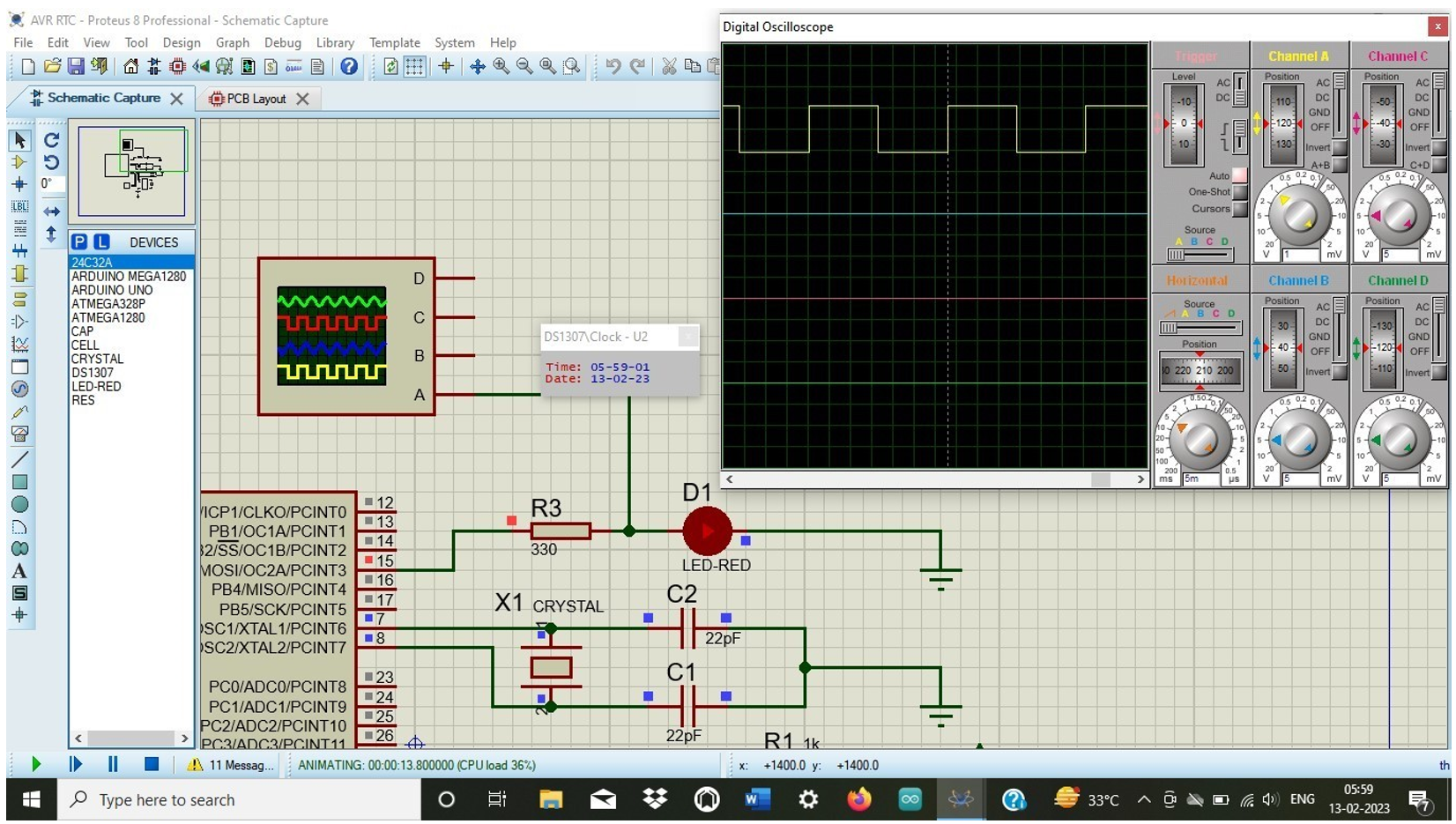
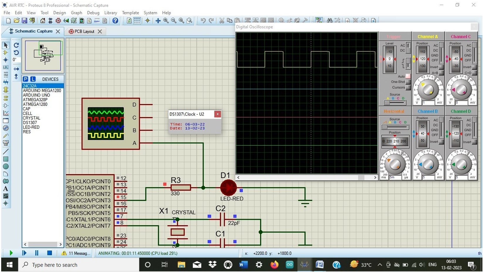
These results confirm that the firmware correctly generates the expected control signal based on RTC timing conditions. Using the same logic then implemented and validated on the physical hardware prototype.
The circuit is implemented on a custom PCB designed in KiCad. The circuit board includes the Arduino Nano module, RTC module, LDR sensor module, MOC3021 optocoupler, 470Ω resistor, connectors, and a BT136 TRIAC.
The Arduino Nano is mounted on the PCB and programmed to execute the control logic based on RTC timing conditions. After assembling the PCB, the logic was tested on a working prototype to validate the system behaviour of the control stage.
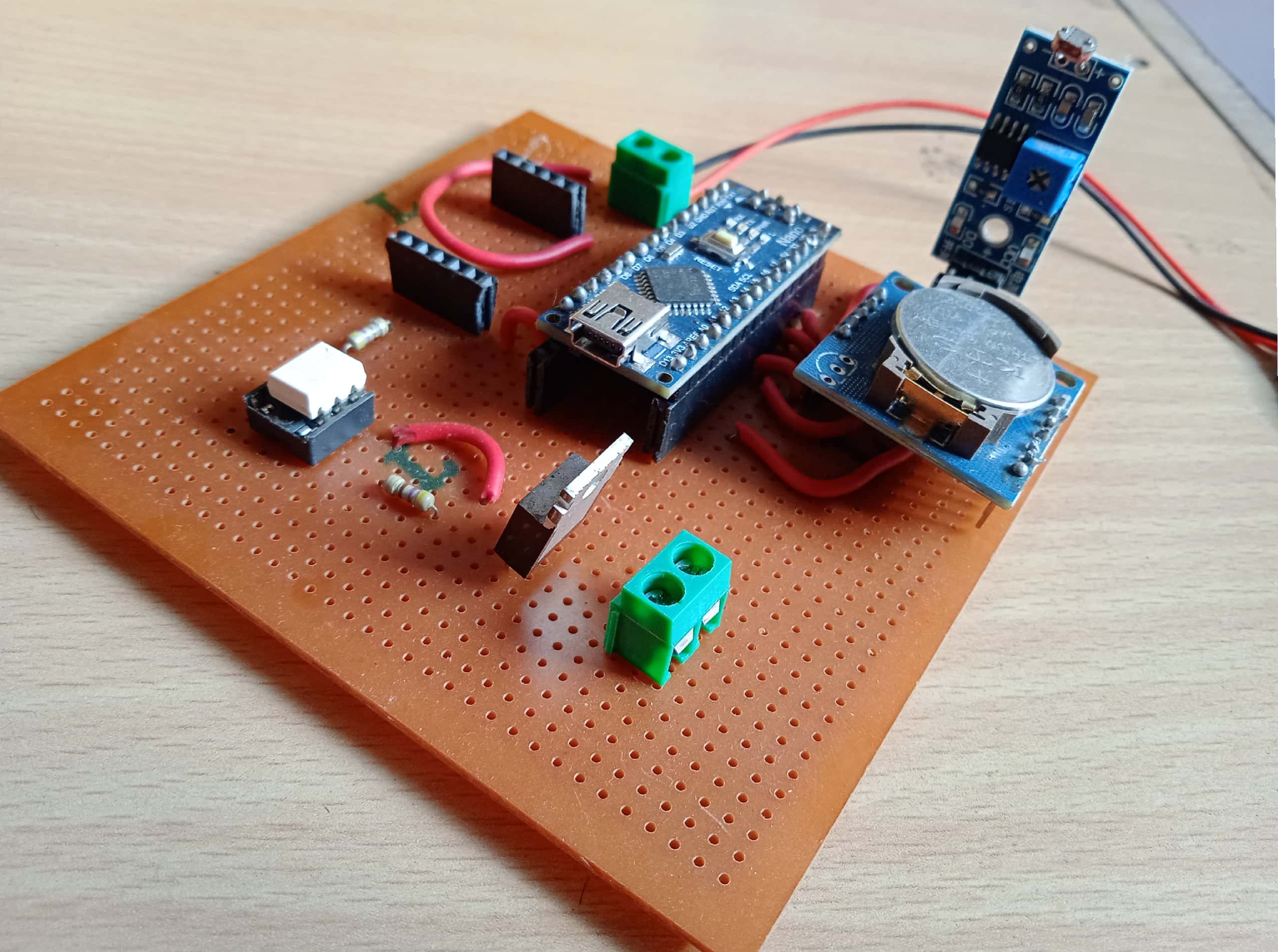
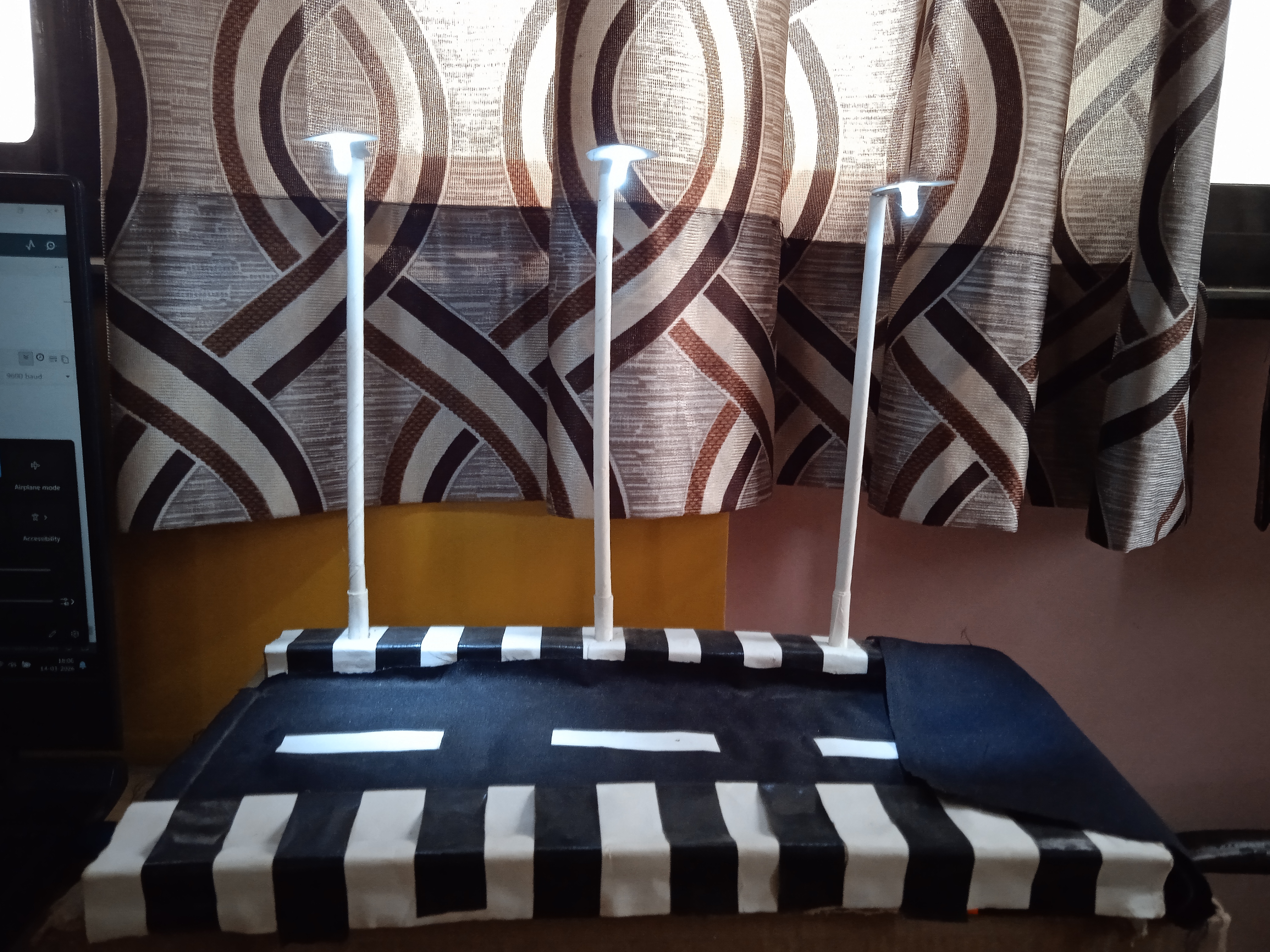
The hardware prototype was tested at different time conditions defined in the firmware. The observed outputs confirm that the system correctly generates the control signal and operates as intended.
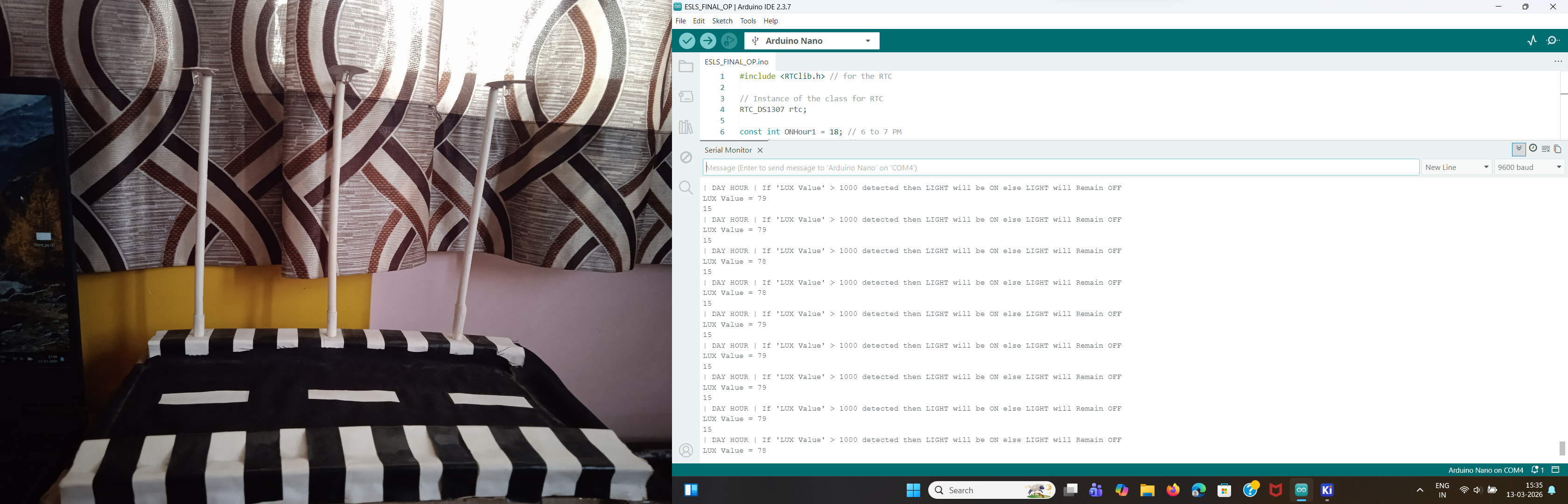
Mechanism is developed in way that during hours from 8 AM to 6 PM Light will remain OFF. In case, operator forgot to switch off main switch still lights will be OFF.
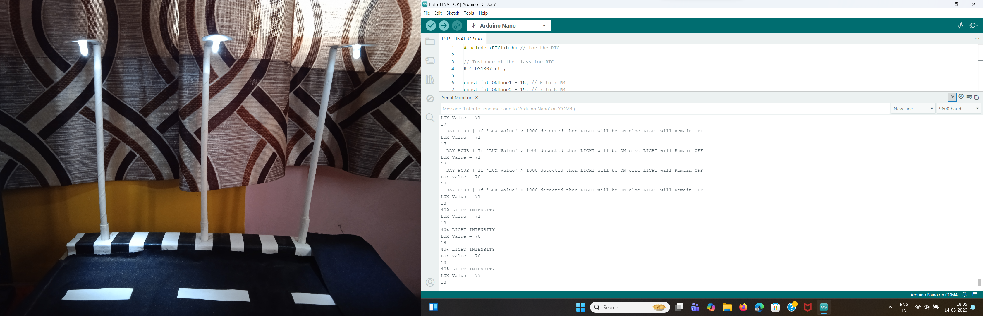
In the evening, during the time of Sunset there is enough light present so, we don't need street lights with Full intensity, so we have make sure that lights will be ON with bit less intensity like at 6-7 PM = 40% & 7-8 PM = 50%. Same logic is used during Sunrise time as well.
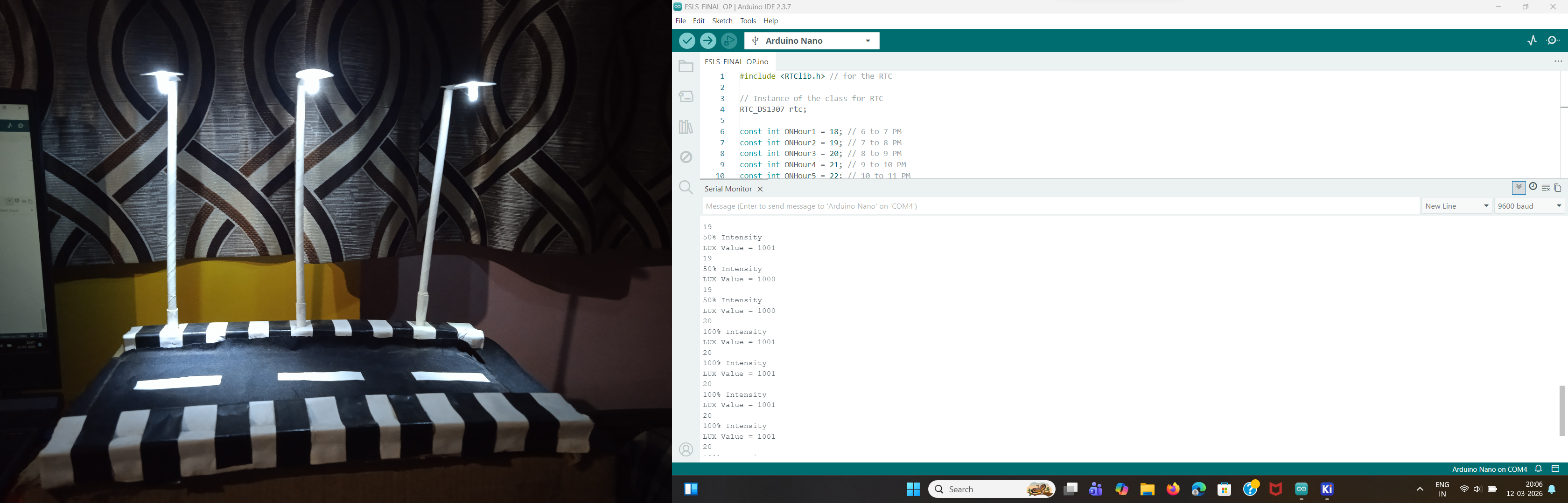
Only During complete DARK hours mainly from 8 PM to 5 AM Lights will be ON with Full intensity.
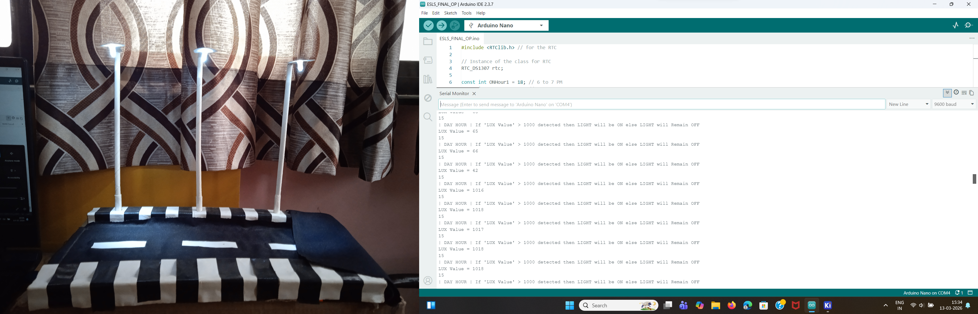
This is a special case designed for Rainy Season, where if clouds appear in Day hours incase if LDR senses surrounding is DARK it will Turn ON lights Automatically without any need Manual workers risking their life in Rainy times.
Developed a system that will use RTC (Real Time Clock) and surrounding ambience with LDR Sensor intelligently and will make sure Light will be ON only during DARK Hours in case of DAY Hours it will be ON but, with less intensity. Which will,
| Qty | Value | Footprint | References |
|---|---|---|---|
| 2 | 470 | Resistor_THT:R_Axial_DIN0207_L6.3mm_D2.5mm_P10.16mm_Horizontal | R1, R2 |
| 2 | Conn_01x05_Socket | Connector_PinSocket_2.54mm:PinSocket_1x05_P2.54mm_Vertical | J2, J3 |
| 2 | Screw_Terminal_01x02 | SnapEDA:TE_282837-2 | J1, J5 |
| 1 | Arduino_Nano_v3.x | Module:Arduino_Nano | A1 |
| 1 | BT136-600 | Package_TO_SOT_THT:TO-220-3_Vertical | Q1 |
| 1 | Conn_01x03_Socket | Connector_PinSocket_2.54mm:PinSocket_1x03_P2.54mm_Vertical | J4 |
| 1 | DS1307+ | Package_DIP:DIP-8_W7.62mm | U1 |
| 1 | MOC3021M | SnapEDA:DIP762W45P254L889H508Q6_MOC3021 | U2 |
It measures 90 × 64.5 mm and has 2 copper layers, 1.6 mm thick.
11 parts, built around the BT136-600E, DS1307+ and MOC3021M. The full list of its parts is on this page, with links to each part's symbol and footprint where PCBKit's library has them.
From the Rajcr2/ESLS repository on GitHub, at the commit this page was made from: the board is ESLS.kicad_pcb. PCBKit opens the board in the browser, with nothing to install.
Its repository publishes it under the MIT licence: you may reuse it on that licence's terms (keep the author's notice, and for a copyleft licence share your changes alike).


kkorzen/Mains-Voltage-Device-Controller
This project was under development during the first semester of Master's Studies at Warsaw University of Technology (Poland) as a final project for Industrial Communication Protocols.

MunyratanakBrorn/Smart-Electrical-Energy-Management-System
Bachelor of Technology Thesis Project 2024.

xicor22/Aaram
PCB design for retro fitting old switch boards with new tech to control it remotely.


