2 layers78.7 × 58.4 mm

 kkorzen/Mains-Voltage-Device-Controller
This project was under development during the first semester of Master's Studies at Warsaw University of Technology (Poland) as a final project for Industrial Communication Protocols.
230V controller is an open-source printed circuit board by kkorzen, from the kkorzen/Mains-Voltage-Device-Controller repository on GitHub, published under the MIT licence. It is a 2-layer board of 85 × 106.5 mm with 38 parts on 54 nets, routed with 264 tracks and 0 vias.
It is built around the BT136-600E, MOC3021M and BC546. Its parts include 11 resistors, 9 diodes, 4 transistors, 4 connectors and 3 switches. It belongs with the AVR (ATmega, ATtiny) boards of this library.


This project was under development during the first semester of Master's Studies at Warsaw University of Technology (Poland) as a final project for Industrial Communication Protocols. Using the UART adaptation of RS-232, a simple controller was created. Its main goal was to make it possible to control a flow of mains current to the load devices. The device contains of two relays for bi-stable control and one triac for more "analogue" control (e.g., a lightbulb dimmer). The heart is an Arduino Nano board.
To make it a complete device with an "easy-to-use" logic, a simple desktop application was created that allows the user to change the states of two included relays and adjust the output voltage of a triac via a slider.
Electronics schematic was made with KiCad. The whole schematic was divided into six sections to clarify different modules of the device.
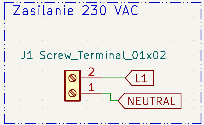
This section contains only a single screw terminal for mains voltage connection. Through this terminal, the mains voltage/current are later delivered to the load devices.
Disclaimer:
"Zasilanie 230 VAC" means "230 VAC power supply".
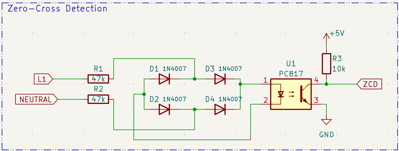
This section, one of the most important, is responsible for detecting the moment when a mains voltage's sine wave is crossing its zero point. As shown in the image given below, as the sine wave has a non-zero value, the optocouple is pulling the ZCD voltage to ground, but at the time the sine has a value of zero the ZCD voltage is pulled high through the 10k resistor $R_3$.
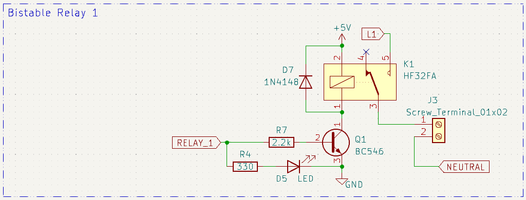
Both of these relays are used to control the power delivery for any load that works with mains voltage. Moreover, it is possible to control any device that takes the mains voltage as the binary control input.
For additional protection, a BJT transistor was used as an element responsible for activating the relay's coil.
When the dimmer module is enabled by setting the DIMMER_EN voltage to HIGH, the optotriac diode is connected to ground, completing the circuit. Then, for a specific period of time, the DIMM_TRIAC voltage is set to HIGH, activating the optotriac. This behavior results in the main triac activating for a specified time, resulting in delivering a specified amount of power to the connected load.
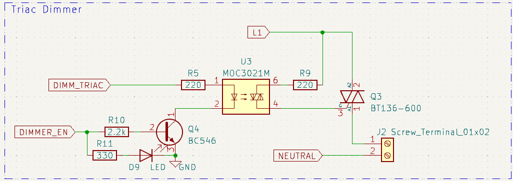
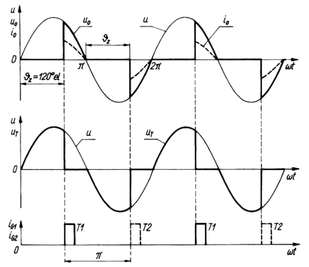
Because the project utilizes a triac, only a resistive load is recommended to avoid the appearance of so-called tail current.
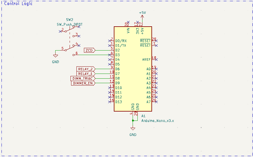
A simple schematic for an Arduino with a drawn pinout. Nothing special, to be honest :sweat_smile:. A button was added to enable and disable dimmer, although the MCU can be reprogrammed to utilize this switch differently.
Both sides of board were utilized, but most of the traces are located on the front. The were two main goals while designed such layout:
The layout can be viewed using one of the free PCB design software, for example KiCad.
Code written for an ATmega328P microcontroller (on an Arduino board) is not anything sophisticated, although it utilizes an ISR for accurate zero-cross detection of mains voltage sine wave.
For communication, it uses a USB protocol (and a USB <> UART transcoder) which, by transmitting and receiving characters, can be controlled by an external desktop app.
In the source code, there is also a potentiometer pinout definition #define POT A0, which was used for manual testing of the dimmer code + circuit combination before the development of the app. It was mounted only on the prototype board (manually soldered on the perfboard) and is not included in the final project.
The range of a triac activation delay (triac_delay) was selected with a so-called trial-and-error method. Values exceeding the range of 300–9000 have been marked as causing the dimmer to be unstable. Feel free to experiment with this range, however please be careful.
It's a simple application - nothing revolutionary, although it was a pretty good micro challenge, which surely gave me an insight into making an app communicating with an external device.
When the app is opened, firstly, an appropriate COM port has to be selected using the combo box and then, by clicking the "Connect" button, the app will (or not if an invalid COM was selected) connect itself with a device, thus enabling the control section (right-hand side of the app's screen).
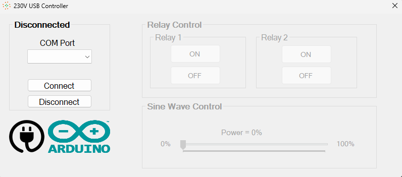
By clicking the "ON" and "OFF" buttons, you can change the state of both relays, respectively. The section below, called "Sine Wave Control", is responsible, as the name suggests, for adjusting the power delivered to the dimmer and its load (read the important warning in the Triac dimmer section).
If the connection is lost or the app is closed without disconnecting, all the relays are turned off and the dimmer power is set to 0%.
| Qty | Value | Footprint | References |
|---|---|---|---|
| 4 | 1N4007 | Diode_THT:D_DO-41_SOD81_P10.16mm_Horizontal | D1, D2, D3, D4 |
| 4 | Screw_Terminal_01x02 | TerminalBlock_Phoenix:TerminalBlock_Phoenix_MKDS-1,5-2_1x02_P5.00mm_Horizontal | J1, J2, J3, J4 |
| 3 | 2.2k | Resistor_THT:R_Axial_DIN0207_L6.3mm_D2.5mm_P10.16mm_Horizontal | R7, R8, R10 |
| 3 | 330 | Resistor_THT:R_Axial_DIN0207_L6.3mm_D2.5mm_P10.16mm_Horizontal | R4, R6, R11 |
| 3 | BC546 | Package_TO_SOT_THT:TO-92_Inline_Wide | Q1, Q2, Q4 |
| 3 | LED | LED_THT:LED_D3.0mm | D5, D6, D9 |
| 2 | 1N4148 | Diode_THT:D_DO-35_SOD27_P7.62mm_Horizontal | D7, D8 |
| 2 | 220 | Resistor_THT:R_Axial_DIN0207_L6.3mm_D2.5mm_P10.16mm_Horizontal | R5, R9 |
| 2 | 47k | Resistor_THT:R_Axial_DIN0207_L6.3mm_D2.5mm_P10.16mm_Horizontal | R1, R2 |
| 2 | HF32FA | My_Footprints:HF32FA_Type1_FormC | K1, K2 |
| 1 | 10k | Resistor_THT:R_Axial_DIN0207_L6.3mm_D2.5mm_P10.16mm_Horizontal | R3 |
| 1 | Arduino_Nano_v3.x | Module:Arduino_Nano | A1 |
| 1 | BT136-600 | Package_TO_SOT_THT:TO-220-3_Vertical | Q3 |
| 1 | MOC3021M | Package_DIP:DIP-6_W7.62mm | U3 |
| 1 | PC817 | Package_DIP:DIP-4_W7.62mm | U1 |
| 1 | SW_Push_DPDT | Button_Switch_THT:SW_Push_2P2T_Toggle_CK_PVA2xxH1xxxxxxV2 | SW2 |
The 34 most common of 38 parts.


MunyratanakBrorn/Smart-Electrical-Energy-Management-System
Bachelor of Technology Thesis Project 2024.

Rajcr2/ESLS
This was my academic project focused on creating a efficient LED based Street Lighting System which will avoid Power Wastage due to manual mismanagement.

xicor22/Aaram
PCB design for retro fitting old switch boards with new tech to control it remotely.


It measures 85 × 106.5 mm and has 2 copper layers, 1.6 mm thick.
38 parts, built around the BT136-600E, MOC3021M and BC546. The full list of its parts is on this page, with links to each part's symbol and footprint where PCBKit's library has them.
From the kkorzen/Mains-Voltage-Device-Controller repository on GitHub, at the commit this page was made from: the board is Controller_PCB/230V_controller.kicad_pcb and its schematic Controller_PCB/230V_controller.kicad_sch. PCBKit opens the board in the browser, with nothing to install.
Its repository publishes it under the MIT licence: you may reuse it on that licence's terms (keep the author's notice, and for a copyleft licence share your changes alike).