2 layers99.8 × 49.8 mm
LedArrayDemo
radex/radmatrix
Tiny modular LED matrix. NOTE: Moved to https://code.hackerspace.pl/radex/radmatrix
453 parts2
 radex/radmatrix2
Tiny modular LED matrix. NOTE: Moved to https://code.hackerspace.pl/radex/radmatrix
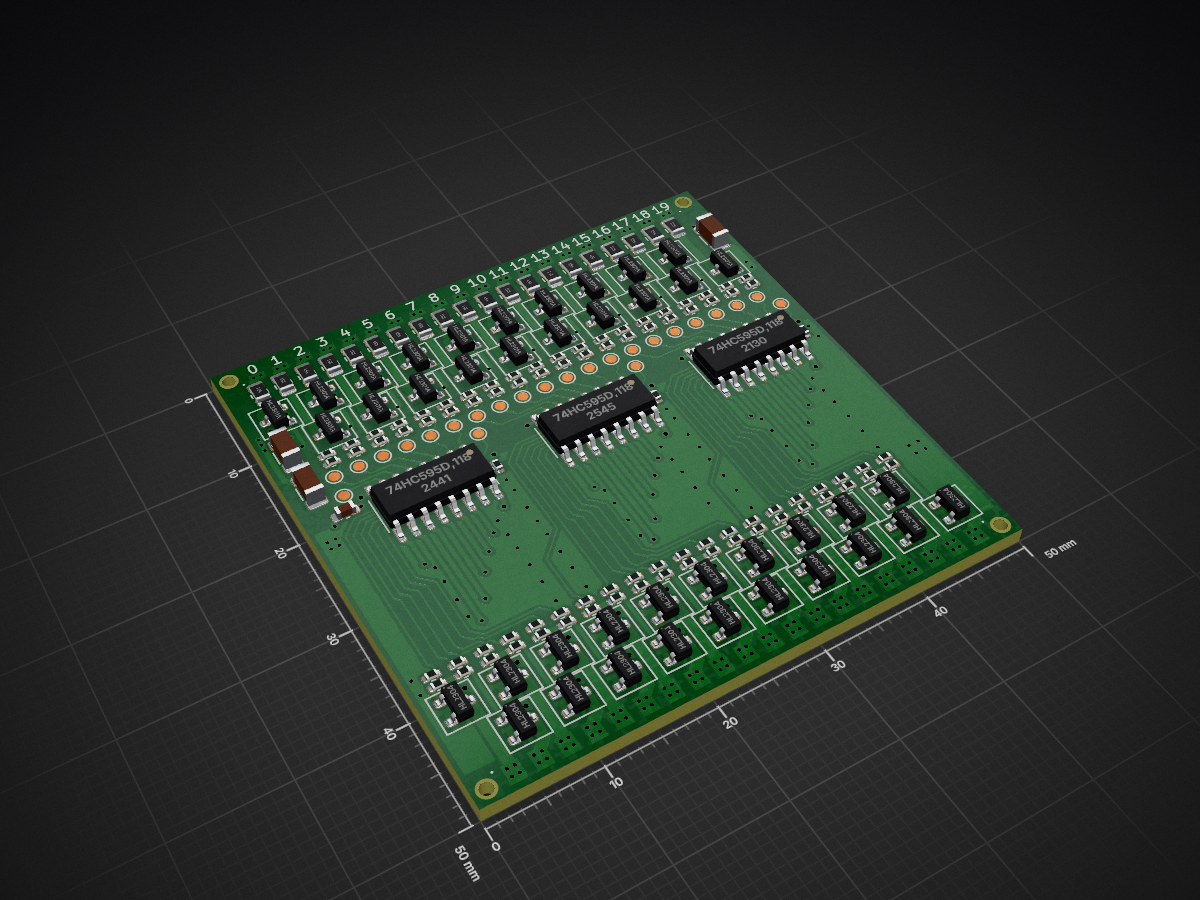
LedArrayMux is an open-source printed circuit board by radex, from the radex/radmatrix repository on GitHub. It is a 2-layer board of 50 × 50 mm with 178 parts on 135 nets, routed with 977 tracks and 321 vias.
It is built around the 74HC595D,118, HL2301A and HL2304. Its parts include 100 resistors, 40 transistors, 7 capacitors and 3 ICs. It belongs with the lEDs and displays boards of this library.


50x50mm microcontroller module, driving LedArrayMux modules. Contains an RP2040 microcontroller, a CAN transceiver, PWM audio output, current sensing, and level shifters to work around LedArrayMux bugs.
Errata:
| Qty | Value | Footprint | References |
|---|---|---|---|
| 40 | 100R | Resistor_SMD:R_0402_1005Metric | R3, R10, R12, R14, R16, R18, R20, R22, R24, R26, R28, R30, R32, R34, R36, R38 +24 |
| 40 | 10k | Resistor_SMD:R_0402_1005Metric | R4, R11, R13, R15, R17, R19, R21, R23, R25, R27, R29, R31, R33, R35, R37, R39 +24 |
| 24 | TestPoint | TestPoint:TestPoint_Pad_D1.0mm | TP1, TP2, TP10, TP11, TP12, TP13, TP14, TP15, TP16, TP17, TP18, TP19, TP20, TP21, TP22, TP23 +8 |
| 20 | 150R | Resistor_SMD:R_0805_2012Metric | R89, R90, R91, R92, R93, R94, R95, R100, R101, R102, R103, R104, R105, R106, R107, R108 +4 |
| 20 | HL2301A | PCM_Package_TO_SOT_SMD_AKL:SOT-23 | Q2, Q3, Q4, Q5, Q10, Q11, Q12, Q13, Q14, Q15, Q16, Q17, Q18, Q19, Q20, Q21 +4 |
| 20 | HL2304 | PCM_Package_TO_SOT_SMD_AKL:SOT-23 | Q1, Q22, Q23, Q24, Q25, Q26, Q27, Q28, Q29, Q30, Q31, Q32, Q33, Q34, Q35, Q36 +4 |
| 4 | , , , | ||
| 3 | 100n | Resistor_SMD:R_0402_1005Metric | C1, C2, C7 |
| 3 | 22uF | Capacitor_SMD:C_1206_3216Metric | C4, C101, C102 |
| 3 | 74HC595D,118 | Package_SO:SO-16_3.9x9.9mm_P1.27mm | U1, U2, U7 |
| 1 | 10u | Capacitor_SMD:C_0603_1608Metric | C6 |
It measures 50 × 50 mm and has 2 copper layers, 1.6 mm thick.
178 parts, built around the 74HC595D,118, HL2301A and HL2304. The full list of its parts is on this page, with links to each part's symbol and footprint where PCBKit's library has them.
From the radex/radmatrix repository on GitHub, at the commit this page was made from: the board is pcb/LedArrayMux/LedArrayMux.kicad_pcb and its schematic pcb/DemoBoard1/LedArrayDemo.kicad_sch. PCBKit opens the board in the browser, with nothing to install.
Its repository states no licence, so its author keeps all rights: ask radex before reusing the design.
radex/radmatrix
Tiny modular LED matrix. NOTE: Moved to https://code.hackerspace.pl/radex/radmatrix

radex/radmatrix
Tiny modular LED matrix. NOTE: Moved to https://code.hackerspace.pl/radex/radmatrix

radex/radmatrix
Tiny modular LED matrix. NOTE: Moved to https://code.hackerspace.pl/radex/radmatrix

BYU-I-eBadge/e-badge
A hackable eBadge platform for students — a customizable, programmable electronics badge designed for hands-on learning and creative exploration throughout their academic journey.


depau/leviot-hw
WIP - first revision HAS ISSUES - Levoit Air Purifier Custom IoT PCB - based on ESP32

ts-manuel/iMX6-Demo-Board
Demo board for the i.MX6ULL Single-Core Processor with Arm Cortex-A7 Core

adaand00/christmas-banana-synth
The Christmas banana synth is a stylophone synthesizer with 24 keys and a buzzer for sound. The back features PCB art of a winter landscape. There are also 12 built-in songs available.

kvoit/FloorHeatingController_HW
Contoller board for up to 10 floor heading circuits. Thermostats via MQTT or 868MHz RF (to be developed). Changed from 1-Wire to 868MHz connectivity in version 2.0.