4 layers64.2 × 66.2 mm

 ICRS/IC-Hack-Badge24
Badges made for the largest Student run hackathon in europe
Badge v2 is an open-source printed circuit board by ICRS, from the ICRS/IC-Hack-Badge repository on GitHub. It is a 2-layer board of 70 × 100 mm with 233 parts on 119 nets, routed with 1,449 tracks and 353 vias.
It is built around the RP2040, SY8089A1AAC and 74HC595D,118, with the USBLC6-2SC6, DO2302E-Q and NRVB130T1G among its other parts. Its parts include 143 diodes, 36 resistors, 19 capacitors, 8 connectors and 7 ICs. It belongs with the lEDs and displays boards and the RP2040 boards of this library.


Repository for how to use and program the IC Hack PCB badges. They are functionally very similar to the Raspberry Pi Pico, and any guides for that board will likely work for this one too.
Microcontrollers are small but flexible computers that are great at interacting with the real world. We hope that by giving everyone a powerful microcontroller like the RP2040, they are able to give embedded programming a go and make something cool!
Kits of sensors and electronics are available from ICRS to help build whatever you have in mind. ICRS can also provide knowledge and help with anything relating to hardware projects and the badges.
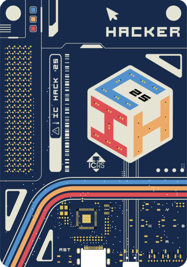
The badges were designed using KiCad and all the design files and schematics are available in the /Hardware folder.
The features of the board are listed below:
The functions of each pin are shown here from the back side.
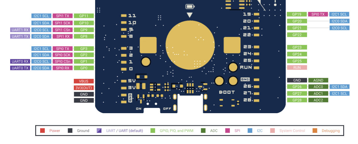
These pins can be connected to using standard Dupont 2.54mm jumper cables.
There are also pins that connect to things internally on the board:
| Pin Number | Function |
|---|---|
| 0 | Button Y |
| 1 | Button B |
| 2 | Button X |
| 3 | Button A |
| 4 | Logo H |
| 5 | Logo C |
| 6 | Logo I |
| 15 | Display serial data |
| 16 | Display enable |
| 17 | Display serial clock |
| 18 | Display latch |
There are several ways of programming the board using either C/C++ or MicroPython.
Arduino is an open source platform for programming microcontrollers in C++. An Arduino library has been written for the board that makes using the built in LED matrix easy.
To get started, download Arduino.
Once you have it running go to file > preferences and add the following link to Additional boards manager URLs: https://github.com/earlephilhower/arduino-pico/releases/download/global/package_rp2040_index.json
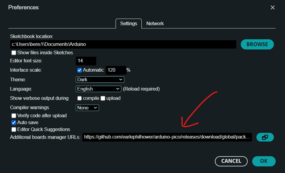
You then need to install support for the RP2040 by going to the board manager tab on the left, searching for "Raspberry Pi Pico" and installing the one by Earle F. Philhower, III.
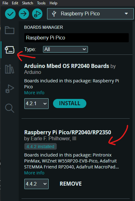
Go to the board selector in the top, and set the current board to the Raspberry Pi Pico.
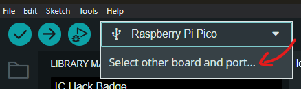
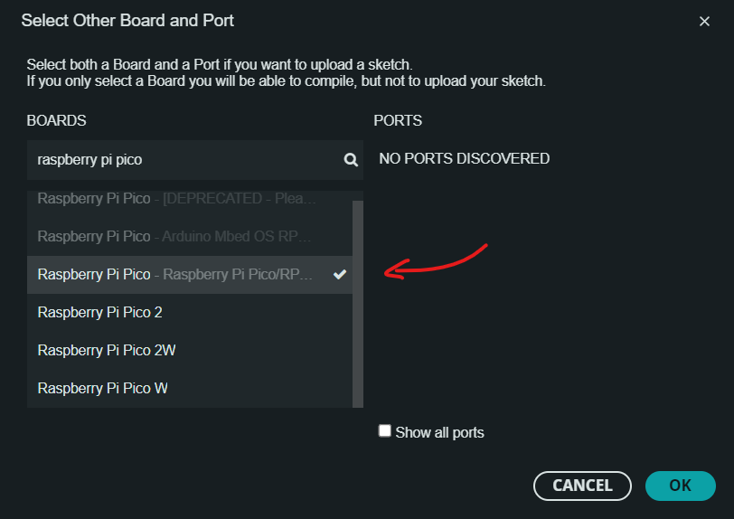
Finally, we need to install the library made for this board by going to the library manager tab on the left, searching for IC Hack Badge, and installing the most recent version.
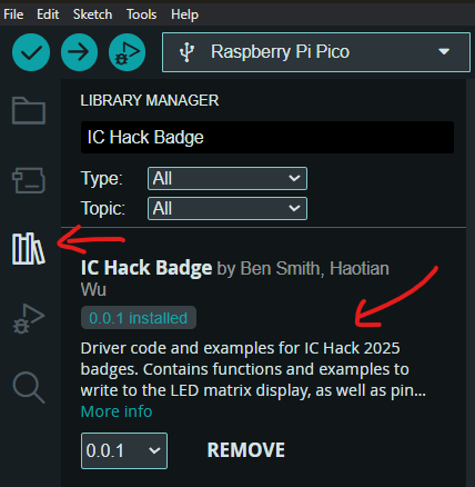
You can then check out example code in File > Examples > IC Hack Badge, or start writing your own code.
To program the badge, put the board in boot mode and select the port it is connected to through the same menu where you chose the current board. You may need to check the Show all ports box. Then press the upload arrow in the top left.
To use MicroPython first upload the interpreter to the badge using the latest firmware from Raspberry Pi, which you can upload using the instructions in Uploading Code & Boot Mode.
You can then connect to the serial port using a program such as PuTTY on Windows, or Minicom on Linux, and start executing code in the MicroPython shell.
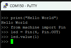
Here we are printing "Hello World" over USB, and then setting pin 4 high, which turns on the H LEDs on the badge's logo. The mapping of pins to their functions is shown in the Pinout section.
You can use the MicroPico VS Code extension, or Thonny to write programs that you can then upload to the badge.
See the documentation by Raspberry Pi for more info and APIs.
Currently there is no MicroPython code for writing to the LED matrix, but both the Arduino library and the default firmware have implementations in C++ that could be ported to Python.
The C/C++ SDK is the official way released by Raspberry Pi for programming the RP2040 microcontroller. It offers more depth and features than Arduino, but lacks Arduino's abstractions and libraries, that can make using it harder.
Setting it up can be a bit more challenging than using Arduino too (especially on Windows), and we recommend following Raspberry Pi's guides if you want to do so.
The firmware flashed to all the badges was written using the C/C++ SDK, and can be found in the /SDK folder for reference. Sorry for the spaghetti, blame Haotian -_-
Plug the board into a computer using the USB C connector. Then in order to program the board it needs to be put into "boot mode". This is done by holding down both the reset button (RST) on the top of the board and the boot button (BOOT) on the bottom of the board. Then release RST, wait a bit and release BOOT.
This will make the board show up as a USB drive that you can drag and drop compiled uf2 binaries into.
The default firmware is firmware.uf2 and you can upload it to your badge with a USB C cable after putting it in boot mode.
Coin cells are able to supply a maximum of around 10mA continuously (ideally <2mA), but the RP2040 when running at full speed can draw well over 20mA. This means that the power consumption needs to be lowered by changing the CPU frequency and voltage so it can be run on the battery.
This can be done in C/C++ using the following lines:
#include "pico/stdlib.h"
#include "hardware/vreg.h"

void main() {
  vreg_set_voltage(VREG_VOLTAGE_0_90);
  set_sys_clock_khz(18000, false);
  ...
}
This lowers the core voltage to 0.9V, and the core frequency to 18MHz which draws around 6mA. This was found to be a good balance of low power and stablility, however it means the USB is disabled since it requires a minimum of 48MHz.
[!NOTE] The battery should last for well over 24 hours with the default firmware, so it can be left on for the whole hackathon.
Using the pico extras repo in the C/C++ SDK (sadly not in Arduino) the chip can be put to sleep which only draws 0.7mA. You can find out more about pico_sleep here.
When running MicroPython the RP2040 consumes too much power for the battery, so you should use USB instead.
Hardware: Ben Smith
Artwork: Anna Votin and Kevin Wang
Firmware: Haotian Wu (+ Ben Smith)
| Qty | Value | Footprint | References |
|---|---|---|---|
| 127 | RED | LED_SMD:LED_0402_1005Metric | D1, D10, D11, D100, D101, D102, D103, D104, D105, D106, D107, D108, D109, D110, D111, D112 +111 |
| 19 | 680R | Resistor_SMD:R_0402_1005Metric | R1, R2, R3, R4, R5, R6, R10, R11, R12, R17, R30, R32, R33, R35, R36, R38 +3 |
| 10 | 100n | Capacitor_SMD:C_0402_1005Metric | C6, C7, C8, C9, C10, C11, C12, C13, C15, C16 |
| 7 | BLUE | LED_SMD:LED_0402_1005Metric | D137, D138, D139, D140, D141, D142, D143 |
| 7 | ORANGE | LED_SMD:LED_0402_1005Metric | D123, D124, D125, D126, D127, D128, D129 |
| 6 | 100k | Resistor_SMD:R_0402_1005Metric | R15, R16, R28, R31, R34, R37 |
| 6 | TS-1089S | badge_footprints:TS-1089S | SW1, SW2, SW3, SW4, SW5, SW6 |
| 6 | ~ | badge_footprints:X6511FRS-04-C85D30 | J1, J2, J3, J4, J5, J6 |
| 5 | 1k | Resistor_SMD:R_0402_1005Metric | R19, R20, R21, R22, R23 |
| 4 | DO2302E-Q | Package_TO_SOT_SMD:SOT-23 | Q1, Q3, Q4, Q5 |
| 4 | TestPoint_Small | TestPoint:TestPoint_Pad_D3.0mm | TP1, TP2, TP3, TP6 |
| 3 | 27R | Resistor_SMD:R_0402_1005Metric | R18, R26, R27 |
| 3 | 2u2 | Capacitor_SMD:C_0402_1005Metric | C5, C14, C17 |
| 3 | 74HC595D,118 | Package_SO:SOIC-16_3.9x9.9mm_P1.27mm | U1, U2, U3 |
| 2 | 15p | Capacitor_SMD:C_0402_1005Metric | C3, C4 |
| 2 | 22u | Capacitor_SMD:C_0603_1608Metric | C1, C18 |
| 2 | 5k1 | Resistor_SMD:R_0402_1005Metric | R24, R25 |
| 2 | LOGO | LOGO | G***, G*** |
| 2 | NRVB130T1G | Diode_SMD:D_SOD-123F | D121, D122 |
| 1 | 1n | Capacitor_SMD:C_0402_1005Metric | C2 |
| 1 | 22k | Resistor_SMD:R_0402_1005Metric | R29 |
| 1 | 22p | Capacitor_SMD:C_0402_1005Metric | C19 |
| 1 | 2u2 | Inductor_SMD:L_1008_2520Metric | L1 |
| 1 | DO2301E-Q | Package_TO_SOT_SMD:SOT-23 | Q2 |
| 1 | MSK12C02-HB | badge_footprints:MSK12C02-HB | SW7 |
| 1 | MY-2450-01 | badge_footprints:MY-2450-01 | J8 |
| 1 | RP2040 | Package_DFN_QFN:QFN-56-1EP_7x7mm_P0.4mm_EP3.2x3.2mm | U4 |
| 1 | SY8089A1AAC | badge_footprints:SOT95P285X130-5N | U7 |
| 1 | USB-TYPE-C-016 | badge_footprints:USB-TYPE-C-016 | J7 |
| 1 | USBLC6-2SC6 | badge_footprints:SOT95P280X145-6N | U6 |
| 1 | W25Q16JVUXIQ_TR | badge_footprints:SON50P300X200X60-9N | U5 |
| 1 | XL2EL89CMI-111YLC-12M | Crystal:Crystal_SMD_3225-4Pin_3.2x2.5mm | Y1 |
It measures 70 × 100 mm and has 2 copper layers, 1.6 mm thick.
233 parts, built around the RP2040, SY8089A1AAC, 74HC595D,118 and USBLC6-2SC6. The full list of its parts is on this page, with links to each part's symbol and footprint where PCBKit's library has them.
From the ICRS/IC-Hack-Badge repository on GitHub, at the commit this page was made from: the board is Hardware/badge_v2/badge_v2.kicad_pcb and its schematic Hardware/badge_v2/badge_v2.kicad_sch. PCBKit opens the board in the browser, with nothing to install.
Its repository states no licence, so its author keeps all rights: ask ICRS before reusing the design.

johflo/Seeed-LoRa-E5_BME680
Seeed Wio E5 LoraWan BME680 node without seperate MCU. Data from the BM680 is sent through the Helium LoraWan network to Cayenne to visualize the measured data


alphaseneca/cryptick-token-pcb
Hardware schematics, 2-layer PCB layout, and manufacturing files for Cryptick Token — the 100% open-source biometric hardware security key and cryptographic hardware enclave.


