2 layers22 × 20 mm
3117 breakout
r4hulrr/ausign
Real-time Auslan (Australian Sign Language) to English speech translation glove. Built with ESP32-S3, flex sensors, IMU on a custom PCB, and a Bluetooth-connected Python GUI.
19 parts3MIT

 r4hulrr/ausign3
Real-time Auslan (Australian Sign Language) to English speech translation glove. Built with ESP32-S3, flex sensors, IMU on a custom PCB, and a Bluetooth-connected Python GUI.
3117 AUSIGN is an open-source printed circuit board by r4hulrr, from the r4hulrr/ausign repository on GitHub, published under the MIT licence. It is a 4-layer board of 60 × 60 mm with 151 parts on 114 nets, routed with 851 tracks and 186 vias.
It is built around the ESP32-S3-WROOM-1-N8, CP2102N-A02-GQFN28 and ESDS314DBVR-TP, with the AP2112K-3.3, BQ24074RGTR and LTST-C190KFKT among its other parts. Its parts include 39 resistors, 33 capacitors, 12 connectors, 11 diodes and 9 ICs. It belongs with the sensors and measurement and radio and wireless boards and the ESP32 boards of this library.


Breaking communication barriers for the Australian Deaf community with an affordable, wearable, real-time Auslan-to-speech translation glove. Check out the demo video.
AUSIGN is a wearable assistive technology device designed to translate Australian Sign Language (Auslan) into spoken English in real time, enabling smoother and more natural communication for deaf and non-verbal individuals.
Unlike existing ASL-centric devices, AUSIGN is purpose-built for Auslan, incorporating contextual awareness via a heart-rate sensor, low-latency audio feedback, and Bluetooth connectivity for flexible output through a mobile/desktop app.
High Level Diagram
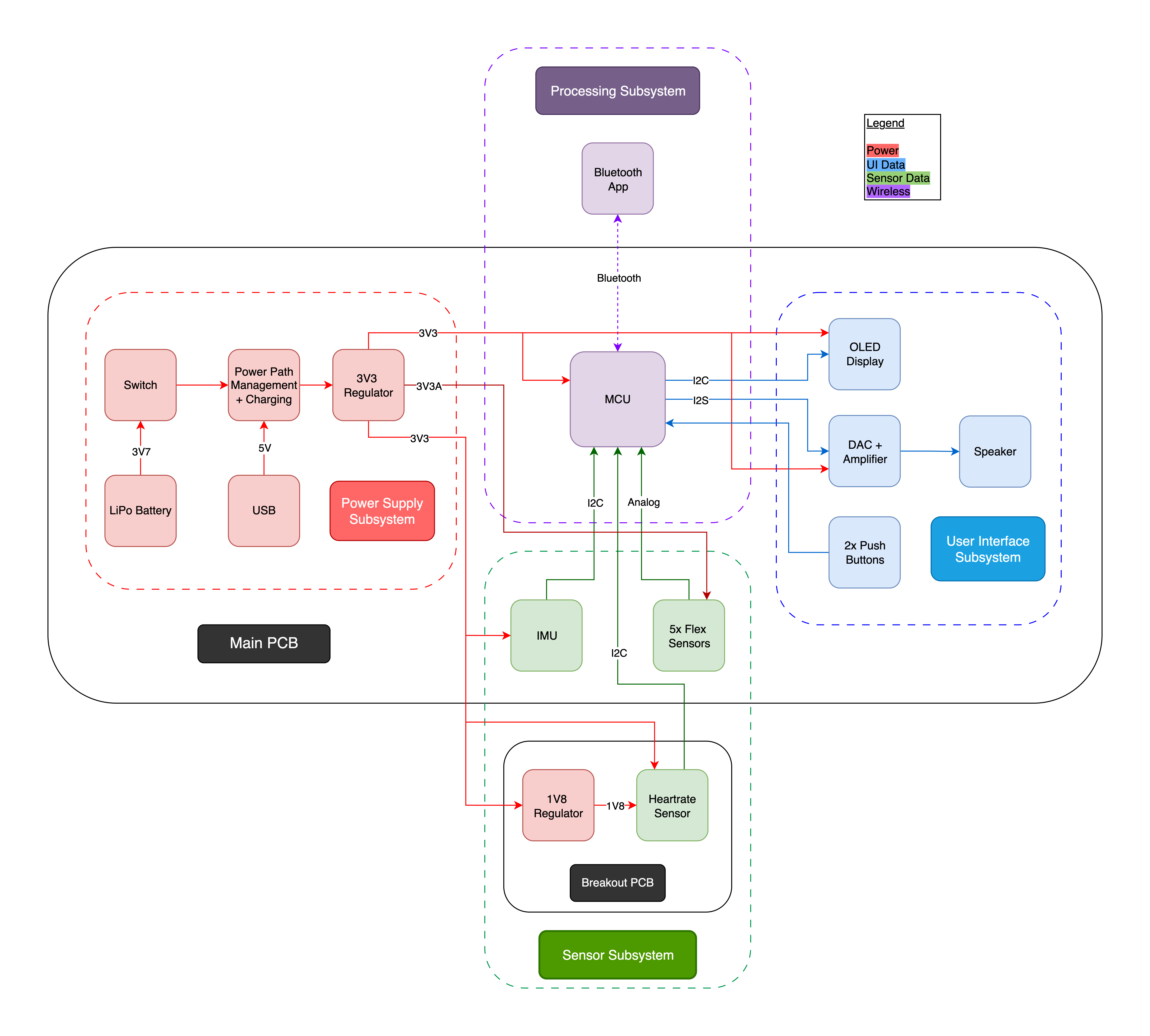
Hardware
Software
├── firmware/ # ESP32-S3 C++ firmware (Arduino/ESP-IDF)
│ ├── src # Contains the main esp32 code along with test code for every component
│ ├── partitions # Custom partition implemented for our 16MB Flash size
├── gui/ # Python BLE GUI application
│ ├── frontend.py # main GUI script
│ ├── signs.csv # Sign definition mappings
│ └── ...
├── hardware/ # PCB schematics and board layouts
│ ├── main_board/
│ ├── breakout_board/
├── demo # Demo video
│ ├── demo_video.mp4
├── docs/ # design docs
└── LICENSE
└── README.mdCheck out the demo video to see AUSIGN in action.
This project is licensed under the MIT License.
“Technology is best when it brings people together.” – AUSIGN aims to bridge the communication gap and foster inclusion through engineering innovation.
| Qty | Value | Footprint | References |
|---|---|---|---|
| 28 | TestPoint | TestPoint:TestPoint_Pad_D1.0mm | 3V3, 3V3A, BOOT, BTN1, BTN2, CH3, CH4, CH5, CH6, CH7, DTR, EN, GND, RTS, RX, SCL0 +12 |
| 20 | 100n | Capacitor_SMD:C_0603_1608Metric | C1, C2, C11, C14, C15, C20, C21, C22, C23, C24, C25, C26, C27, C28, C30, C31 +4 |
| 16 | 10k | Resistor_SMD:R_0603_1608Metric | R8, R20, R21, R22, R23, R25, R26, R27, R28, R29, R31, R32, R33, R34, R35, R39 |
| 6 | JST_SH_2P | Connector_JST:JST_SH_SM02B-SRSS-TB_1x02-1MP_P1.00mm_Horizontal | J4, J5, J6, J7, J8, J9 |
| 5 | 1u | Capacitor_SMD:C_0603_1608Metric | C4, C5, C10, C18, C34 |
| 5 | LTST-C190KFKT | LED_SMD:LED_0603_1608Metric | D5, D6, D13, D14, D15 |
| 4 | 1k | Resistor_SMD:R_0603_1608Metric | R13, R14, R30, R37 |
| 4 | 200 | Resistor_SMD:R_0603_1608Metric | R11, R42, R43, R44 |
| 4 | 4k7 | Resistor_SMD:R_0603_1608Metric | R5, R6, R50, R51 |
| 4 | 4u7 | Capacitor_SMD:C_0603_1608Metric | C3, C9, C12, C13 |
| 4 | MountingHole | MountingHole:MountingHole_2.2mm_M2 | H1, H2, H3, H4 |
| 4 | PTS815SJK250SMTR | PTS815SJK250SMTR:PTS815SJK250SMTR | SW1, SW2, SW3, SW4 |
| 3 | 499 | Resistor_SMD:R_0603_1608Metric | R2, R3, R4 |
| 3 | ESDS314DBVR | Package_TO_SOT_SMD:SOT-23-5 | U4, U7, U10 |
| 3 | LTST-C190KGKT | LED_SMD:LED_0603_1608Metric | D4, D7, D10 |
| 3 | SolderJumper_2_Open | Jumper:SolderJumper-2_P1.3mm_Open_RoundedPad1.0x1.5mm | JP1, JP2, JP5 |
| 3 | SolderJumper_3_Open | Jumper:SolderJumper-3_P1.3mm_Open_RoundedPad1.0x1.5mm | JP3, JP4, JP8 |
| 2 | 1.5k | Resistor_SMD:R_0603_1608Metric | R9, R10 |
| 2 | 10u | Capacitor_SMD:C_0603_1608Metric | C6, C35 |
| 2 | 22u | Capacitor_SMD:C_0603_1608Metric | C32, C33 |
| 2 | 5k1 | Resistor_SMD:R_0603_1608Metric | R16, R17 |
| 2 | SS8050 | Package_TO_SOT_SMD:SOT-23 | Q2, Q3 |
| 1 | 100k | Resistor_SMD:R_0603_1608Metric | R7 |
| 1 | 22k1 | Resistor_SMD:R_0603_1608Metric | R18 |
| 1 | 47k5 | Resistor_SMD:R_0603_1608Metric | R19 |
| 1 | 634k | Resistor_SMD:R_0603_1608Metric | R47 |
| 1 | AP2112K-3.3 | Package_TO_SOT_SMD:SOT-23-5 | U1 |
| 1 | BLM18AG601SN1D | Inductor_SMD:L_0603_1608Metric | FB1 |
| 1 | BQ24074RGT | Package_DFN_QFN:VQFN-16-1EP_3x3mm_P0.5mm_EP1.6x1.6mm | U3 |
| 1 | CP2102N-A02-GQFN28 | Package_DFN_QFN:QFN-28-1EP_5x5mm_P0.5mm_EP3.35x3.35mm | U6 |
| 1 | Conn_01x02_Pin | Connector_PinHeader_2.54mm:PinHeader_1x02_P2.54mm_Vertical | J12 |
| 1 | Conn_01x04_Pin | Connector_PinHeader_2.54mm:PinHeader_1x04_P2.54mm_Vertical | J10 |
| 1 | Conn_01x04_Socket | Connector_PinSocket_2.54mm:PinSocket_1x04_P2.54mm_Vertical | J11 |
| 1 | ESP32-S3-WROOM-1 | RF_Module:ESP32-S3-WROOM-1 | U8 |
| 1 | IRLML6402TRPBF | Package_TO_SOT_SMD:SOT-23W | Q1 |
| 1 | JST_PH_2P | JST_PH_2P:JST_PH_2P | J1 |
| 1 | JST_SH_4P | Connector_JST:JST_SH_SM04B-SRSS-TB_1x04-1MP_P1.00mm_Horizontal | J2 |
| 1 | LSM6DSOTR | Package_LGA:LGA-14_3x2.5mm_P0.5mm_LayoutBorder3x4y | U2 |
| 1 | MAX98357A | Package_DFN_QFN:TQFN-16-1EP_3x3mm_P0.5mm_EP1.23x1.23mm | U9 |
| 1 | MMBZ5233BLT1G | MMBZ5233BLT1G:MMBZ5233BLT1G | D1 |
| 1 | OS102011MS2QN1 | OS102011MS2QN1:OS102011MS2QN1 | SW6 |
| 1 | SMF5.0A | Diode_SMD:D_SOD-123F | D3 |
| 1 | SP0503BAHT | SP0503BAHTG:SP0503BAHTG | D9 |
| 1 | USB4105-GF-A | Connector_USB:USB_C_Receptacle_GCT_USB4105-xx-A_16P_TopMnt_Horizontal | J3 |
r4hulrr/ausign
Real-time Auslan (Australian Sign Language) to English speech translation glove. Built with ESP32-S3, flex sensors, IMU on a custom PCB, and a Bluetooth-connected Python GUI.

r4hulrr/ausign
Real-time Auslan (Australian Sign Language) to English speech translation glove. Built with ESP32-S3, flex sensors, IMU on a custom PCB, and a Bluetooth-connected Python GUI.


dragon-mobile/solid_state_relays_12v
The Solid State Relays - 12Volts is an open hardware solid state relay PCB aimed at the tiny home, van life and maker communities.


ENEL-400/PCB
A production-oriented KiCad template aligned with JLCPCB's PCB fabrication capabilities, using minimum design rules for cost-effective prototyping and manufacturing.

Soulboy420/BP_flappyBird
Eigenständiger KiCad-10-Entwurf für das HAW-Bachelorprojekt. Der ursprüngliche Entwurf unter hardware/ und absichtliche Benutzerlöschungen wurden nicht überschrieben. Es wurde nichts bestellt, committed oder gepusht.

noahzhy/cc_glasses
tools/ 为此次整改的重建和检查脚本;日常直接编辑 KiCad 工程。重建脚本会覆盖设计,不能在人工修改后直接重跑。Python 工具不引入继承类;需要 KiCad 10 的 pcbnew Python,以及 Python 3 的 sexpdata、numpy、scipy、shapely、pymupdf。

It measures 60 × 60 mm and has 4 copper layers, 1.6 mm thick.
151 parts, built around the ESP32-S3-WROOM-1-N8, CP2102N-A02-GQFN28, ESDS314DBVR-TP and AP2112K-3.3. The full list of its parts is on this page, with links to each part's symbol and footprint where PCBKit's library has them.
From the r4hulrr/ausign repository on GitHub, at the commit this page was made from: the board is hardware/main-board/3117_AUSIGN.kicad_pcb and its schematic docs/weekly_tasks/task-pcb-files/ELEC3117_Template.kicad_sch. PCBKit opens the board in the browser, with nothing to install.
Its repository publishes it under the MIT licence: you may reuse it on that licence's terms (keep the author's notice, and for a copyleft licence share your changes alike).