4 layers35 × 55.3 mm

 QTC-UMD/dds-sweeper11
Raspberry Pi Pico interface for the AD9959 DDS
Dds sweeper board is an open-source printed circuit board by QTC-UMD, from the QTC-UMD/dds-sweeper repository on GitHub, published under the BSD-2-Clause licence. It is a 2-layer board of 53 × 65 mm with 17 parts on 44 nets, routed with 83 tracks and 0 vias.
It is built around the 74LVC1G17Z and XC6210B182MR. Its parts include 6 capacitors, 6 connectors, 3 ICs and 2 resistors. It belongs with the interfaces and adapters boards and the RP2040 boards of this library.


Raspberry Pi Pico interface for the AD9959 DDS.
If you use this project, please cite as:
E. Huegler, J. C. Hill, and D. H. Meyer, An agile radio-frequency source using internal sweeps of a direct digital synthesizer, Review of Scientific Instruments, 94, 094705 (2023) https://doi.org/10.1063/5.0163342
| Table Mode | 1 Channel | 2 Channel | 3 Channel | 4 Channel |
|---|---|---|---|---|
| Single Stepping | 500 | 750 | 1000 | 1250 |
| Sweep Mode | 1000 | 1500 | 2000 | 2500 |
| Table Mode | 1 Channel | 2 Channel | 3 Channel | 4 Channel |
|---|---|---|---|---|
| Single Stepping | 4 $\mu s$ | 6 $\mu s$ | 8 $\mu s$ | 10 $\mu s$ |
| Sweep Mode | 8 $\mu s$ | 12 $\mu s$ | 16 $\mu s$ | 20 $\mu s$ |
244 kB (RP 2040):
| Table Mode | 1 Channel | 2 Channel | 3 Channel | 4 Channel |
|---|---|---|---|---|
| Single Stepping (Ext Timer) | 16656 | 8615 | 5810 | 4383 |
| Sweep Mode (Ext Timer) | 8614 | 4382 | 2938 | 2210 |
| Single Stepping (Int Timer) | 5000 | 5000 | 5000 | 4032 |
| Sweep Mode (Int Timer) | 5000 | 4032 | 2703 | 2033 |
500 kB (RP 2350):
| Table Mode | 1 Channel | 2 Channel | 3 Channel | 4 Channel |
|---|---|---|---|---|
| Single Stepping (Ext Timer) | 34132 | 17654 | 11905 | 8981 |
| Sweep Mode (Ext Timer) | 17654 | 8981 | 6022 | 4529 |
| Single Stepping (Int Timer) | 5000 | 5000 | 5000 | 5000 |
| Sweep Mode (Int Timer) | 5000 | 5000 | 5000 | 4353 |
Download the latest dds-sweeper_rp2040.uf2 file for Pi Pico or dds-sweeper_rp2350.uf2 file for Pi Pico 2.
On your Raspberry Pi Pico, hold down the "bootsel" button while plugging the Pico into USB port on a PC (that must already be turned on).
The Pico should mount as a mass storage device (if it doesn't, try again or consult the Pico documentation).
Drag and drop the .uf2 file into the mounted mass storage device.
The mass storage device should unmount after the copy completes. Your Pico is now running the DDS Sweeper firmware!
Here is a simplified wiring diagram showing the mapping between Pico pins and the AD9959.
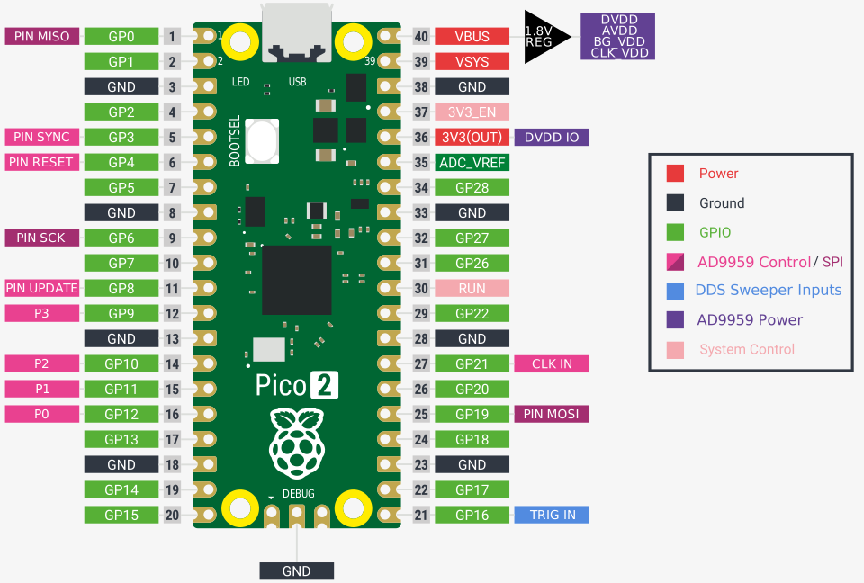
In the dds-sweeper-board directory is a KiCAD project for a simple carrier board
with a socket that aligns directly to the header pins of the AD9959 Eval board.
It is a recommended design for ensuring quality high-speed communication signals between the Pico and AD9959.
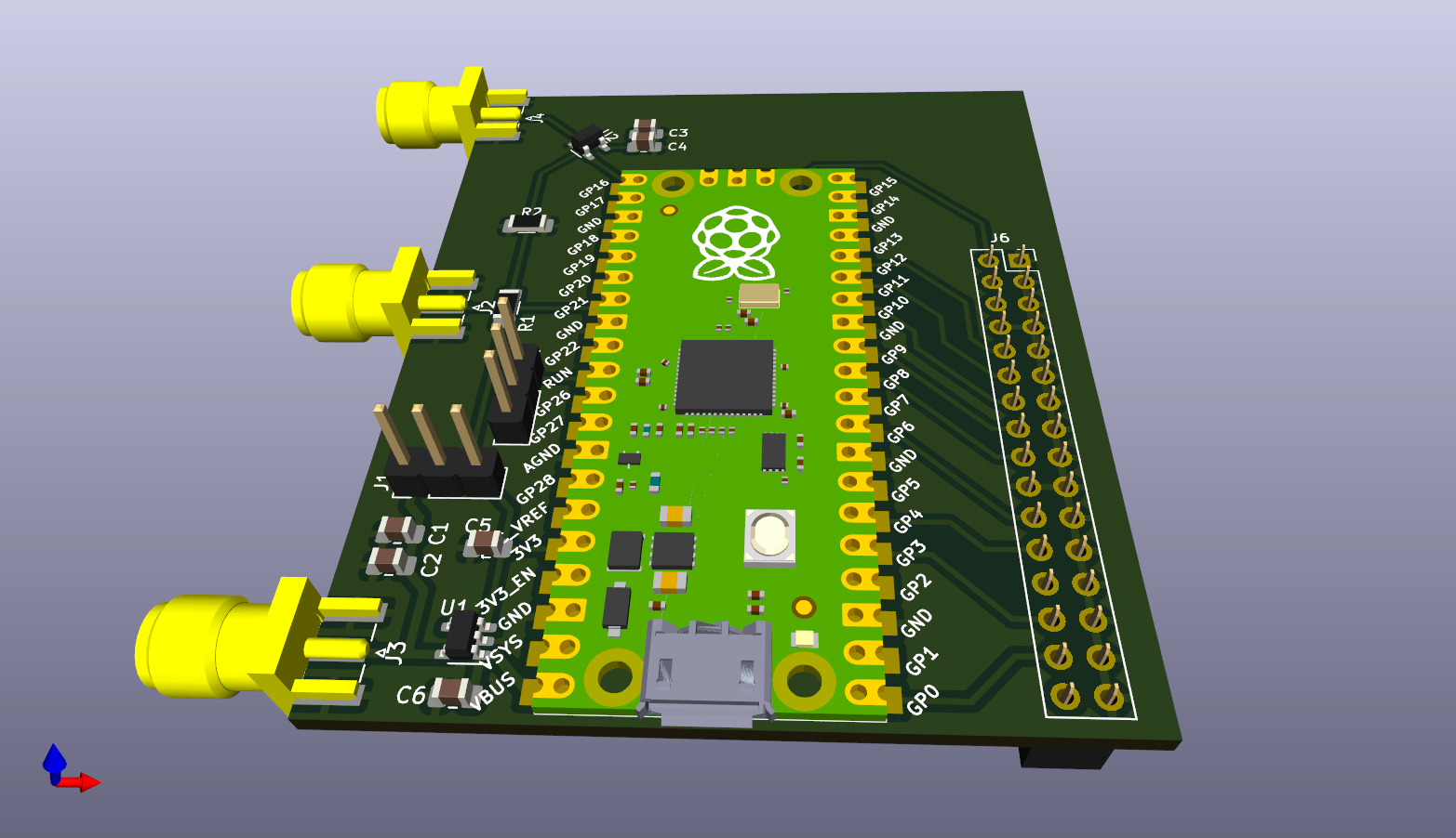
This board has a 3-pin header for connecting 3.3V and 1.8V to the TB1 header of the AD9959 Eval board,
as well as an SMA connected 1.8V for connection to the AVDD analog output power supplies of the board.
Note that the AVDD connections for each channel are electrically connected by the AD9959 Eval PCB,
meaning the 1.8V can be daisy chained with more SMA cables to power the BG_VDD and CLK_VDD inputs.
When the DDS Sweeper is started, configuration is required before it can be used. It is often good to begin with a reset command, which resets the AD9959.
First, the clock should be setup with the setclock command, followed by the setmult command.
Second, the number of channels should be configured with the setchannels command, which sets the number of dynamic channels, and leaves the remaining channels static.
Finally, the mode and timing should be setup with the mode command. The DDS Sweeper uses either discrete amplitude, frequency, and phase steps or sweeps of one parameter (possibly with steps of the other parameter) as its primitive instructions. The DDS Sweeper can then use internal timing (in which case it generates triggers internally after each step or sweep) or external timing (in which case it waits for external triggers).
Once setup is complete, instructions (steps or sweeps, depending on the mode) and timings can be loaded using the set, seti, or setb commands. In addition to output instructions, there are special stop and repeat instructions (which can only be loaded using seti and setb). With instructions are loaded, the address (order in which they are executed) is specified, so the order of loading need not match the order of execution. Timing is set per address, so it is common to all channels. The stop instruction ends program execution, while the repeat instruction restarts program execution from the beginning. Instructions are loaded into an uninitialized array, so skipping instruction addresses or failing to specify stop/repeat at the end of the program may result in undefined behavior.
Finally, the program can be executed using the start or hwstart commands. If termination of the program is required before it reaches a stop command, the abort command can be used.
Output Amplitude is dependent on frequency (some people on Analog Devices forum mentioned amplitude and frequency are related by a sinc function)
The frequency resolution of the AD9959 is $= \frac{f_{sys clk}}{2^{32}}$. At the default system clock of 500 MHz, the frequency resolution is $\approx 0.1164$ Hz. Frequency input to the DDS Sweeper using the set command will be rounded to an integer multiple of the frequency resolution. Frequency input to the DDS Sweeper using the seti or setb commands will be in units of the frequency resolution.
The phase resolution of the AD9959 is $= \frac{360^\circ}{2^{14}} \approx 0.02197^\circ$. Phase offsets given using the set command will be rounded to a multiple of this resolution. Phase offsets given using the seti or setb commands will be in units of this resolution.
The amplitude resolution of the AD9959 is $= \frac{1}{2^{10}} \approx 0.09767%$. Amplitude scale factors given using the set command will be rounded to a multiple of this resolution. Amplitude scale factors given using the seti or setb commands will be in units of this resolution.
When the DDS Sweeper uses internal timing to execute instructions, that time is based on the number of clock cycles of the Pico's system clock (which defaults to 125 MHz for an 8 ns period). Timing inputs using the set command are given in seconds and will be rounded to an integer multiple of the Pico system clock period. Timing input using the seti or setb commands is defined to be in units of the Pico system clock period.
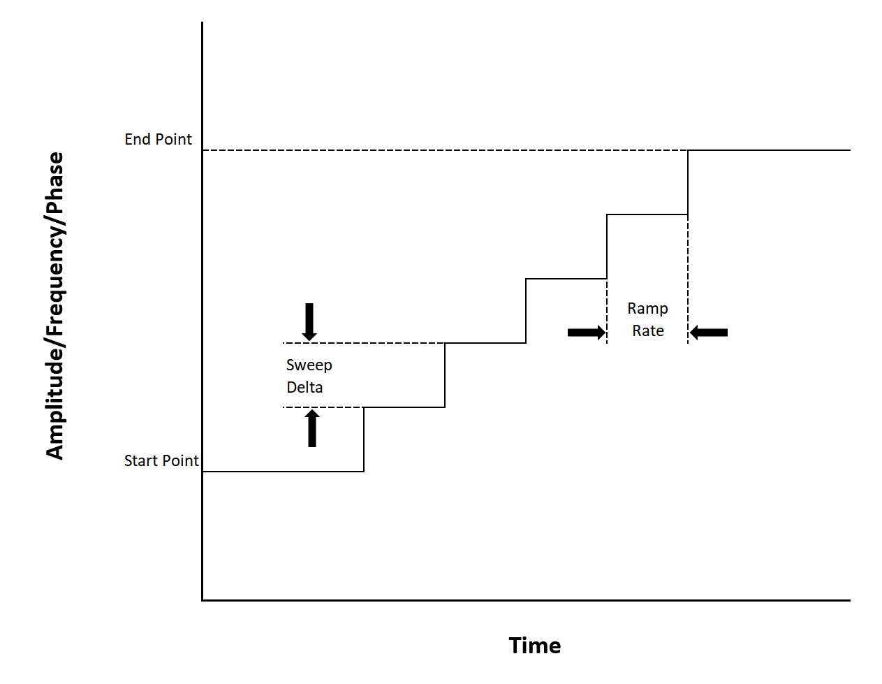
For more details on sweeps, see sweep details.
Note: Commands must be terminated with \n.
version:
Responds with a string containing the firmware version.
status:
Returns the operating status of the DDS-Sweeper.
0: manual mode1: transitioning to buffered execution2: buffered execution3: aborting buffered execution4: last buffered execution was aborted5: transitioning to manual modeclkstatus:
Returns the clocking status of the DDS-Sweeper as three numbers: <int:mode> <double:freq> <int:mult>.
Mode can be 0 for internal clocking or 1 for external clocking of the AD9959.
The frequency is the AD9959 reference frequency, in Hz.
mult is the AD9959 PLL multiplier. The corresponding system frequency is freq*-*mult.
board:
Responds with which type of board the firmware is running on: pico1 or pico2.
getfreqs:
Responds with a multi-line string containing the current operating frequencies of various clocks (you will be most interested in pll_sys and clk_sys). Multiline string ends with ok\n.
start:
Starts buffered execution immediately.
hwstart:
Starts buffered execution once an external trigger is received.
abort:
Stops buffered execution immediately.
setclock <mode:int> <freq:int> (<pll_mult:int>):
Reconfigures the source/reference clock.
0: Use pico system clock as reference to the AD9959.
In this mode, the frequency provided also sets the pico system clock
and it cannot exceed 133 MHz.
The dds sweeper defaults to this mode with a frequency of 125 MHz and a PLL multiplier of 4.1: Sets the AD9959 to receive a reference clock not from the pico.
Setting this mode does not change the pico system clock.pll_mult is an optional input that sets the AD9959's PLL multiplier on the Reference Clock input. The default value is 4, giving the AD9959 a system clock of 500 MHz with the pico's 125 MHz reference. Valid values are 1 or 4-20.
The AD9959's PLL has an output range of 100-160 MHz or 255-500 MHz with VCO gain enabled. The pico will automatically enable the VCO gain bit if the requested frequency is in the upper range. If trying to use the PLL multiplier to generate a frequency between 160 and 255 MHz, there is no guarantee of operation.
setchannels <num:int>:
Sets how many channels being used by the table mode. Uses the lowest channels first, starting with channel 0. If number of channels is set to 0, buffered execution instructions will be written to all 4 channels simultaneously.
mode <sweep-type:int> <trigger-source:int>:
Configures what mode the DDS-Sweeper is operating in
The operating mode must be set before buffered execution instructions can be programmed into the DDS-Sweeper.
A trigger-source of 0 means the Sweeper is expecting external triggers. A trigger-source of 1 means the Sweeper will send its own triggers and set commands will require an additional time argument.
setfreq <channel:int> <frequency:float>:
Manually set the output frequency of a specified channel. Channels are 0-3 and frequencies are in Hz. If debug is set to on, it will respond with the actual frequency set. The Sweeper must be in manual mode.
setphase <channel:int> <phase_offset:float>:
Manually set the phase offset of a specified channel. Channels are 0-3 and offsets are in degrees. If debug is set to on, it will respond with the actual degree offset set. The Sweeper must be in manual mode.
setamp <channel:int> <amplitude_scale_factor:float>:
Manually set the amplitude scale factor of a specified channel. Channels are 0-3 and amplitude scale factors are a precentage of the maximum output voltage. If debug is set to on, it will respond with the actual frequency set. The Sweeper must be in manual mode.
set:
Sets the value of instruction number addr for channel channel (zero indexed). addr starts at 0. It looks different depending on what mode the sweeper is in. If Debug is set to on it will respond with the actual values set for that instruction.
Single Stepping (mode 0): set <channel:int> <addr:int> <frequency:float> <amplitude:float> <phase:float> (<time:float>)
Sweep Mode (modes 1-3): set <channel:int> <addr:int> <start_point:float> <end_point:float> <sweep_rate:float> (<time:float>)
start_point is the value the sweep should start from, and end_point is where it will stop. sweep_rate is the amount that the output should change in each quantity's units per second (further info below). In the AD9959, the sweep clock runs at one quarter the system clock. The types of values expected for start_point, end_point, and sweep_rate are different depending on the type of sweep:
start_point and end_point should be decimals between 0 and 1 that represent the desired proportion of the maximum output amplitude. sweep_rate is then that proportion per second. The resolution of the start and end values is $\frac{1}{1024} \approx 0.09766$.start_point and end_point are frequencies in Hz, with sweep_rate in Hz per second. The start and end points can have decimal values, but they will be rounded to the nearest multiple of the frequency resolution ($\frac{f_{sysclk}}{2^{32}}$).start_point, end_point are in degrees, with sweep_rate in degrees per second. The start and end points can have decimal values, but they will be rounded to the nearest multiple of the phase resolution ($\frac{360^\circ}{2^{14}} \approx 0.02197^\circ$).Sweep and Single Stepping Mode (modes 4-6): set <channel:int> <addr:int> <start_point:float> <end_point:float> <sweep_rate:float> <secondary1:double> <secondary2:double> (<time:float>)
These modes perform a linear sweep on one of the parameters, while simultaneously single stepping on the other two parameters.
secondary1 is the frequency, and secondary2 is the phase offset.secondary1 is the amplitude scale factor, and secondary2 is the phase offset.secondary1 is the frequency, and secondary2 is the amplitude scale factor.seti:
Sets the value of instruction number addr for channel channel (zero indexed). addr starts at 0. It looks different depending on what mode the sweeper is in. If Debug is set to on it will respond with the actual values set for that instruction. seti uses integer values (AD9959 units) rather than floating point values. Otherwise, it is the same as set.
Single Stepping (mode 0): seti <channel:int> <addr:int> <frequency:int> <amplitude:int> <phase:int> (<time:int>)
Sweep Mode (modes 1-3): seti <channel:int> <addr:int> <start_point:int> <end_point:int> <delta:int> <ramp-rate:int> (<time:int>)
start_point is the value the sweep should start from, and end_point is where it will stop. delta is the amount that the output should change by every cycle of the sweep clock. In the AD9959, the sweep clock runs at one quarter the system clock. ramp-rate is an additional divider that can applied to slow down the sweep clock further, must be in the range 1-255. The types of values expected for start_point, end_point, and delta different depending on the type of sweep
start_point and end_point should be integers between 0 and 1023 (inclusive).start_point, end_point, and delta are integers between 0 and $2^{32} - 1$ in units of system clock rate (typically $500$ MHz) over $2^{32}$.start_point, end_point, and delta are between 0 and 65535 (inclusive).Sweep and Single Stepping Mode (modes 4-6): set <channel:int> <addr:int> <start_point:int> <end_point:int> <delta:int> <ramp-rate:int> <secondary1:int> <secondary2:int> (<time:int>)
These modes perform a linear sweep on one of the parameters, while simultaneously single stepping on the other two parameters.
secondary1 is the frequency, and secondary2 is the phase offset.secondary1 is the amplitude scale factor, and secondary2 is the phase offset.secondary1 is the frequency, and secondary2 is the amplitude scale factor.setb <start address:int> <instruction count:int>:
Bulk setting of instructions in binary. start address is the address of the first instruction loaded. instruction count instructions will be programmed. If there is not sufficient space for that many instructions, the response will be an error message. Otherwise, the response will be ready for <byte count:int> bytes, where byte count is the number of bytes the device is expecting. An array of instructions can then be transmitted. Note that all active channels are loaded together. The layout of the instruction array is mode dependent, and in the table below each mode is assumed to use external timing (where internal timing bytes are in parentheses and the dtype list must have , ('time', '<u4') appended)
| Mode | Bytes per channel per instruction | np.dtype |
|---|---|---|
| Single Stepping (mode 0) | 8 (12) | [('frequency', '<u4'), ('amplitude', '<u2'), ('phase', '<u2')] |
| Amplitude Sweeps (mode 1) | 7 (11) | [('start_amplitude', '<u2'), ('stop_amplitude', '<u2'), ('delta', '<u2'), ('rate', '<u1')] |
| Frequency Sweeps (mode 2) | 13 (17) | [('start_frequency', '<u4'), ('stop_frequency', '<u4'), ('delta', '<u4'), ('rate', '<u1')] |
| Phase Sweeps (mode 3) | 7 (11) | [('start_phase', '<u2'), ('stop_phase', '<u2'), ('delta', '<u2'), ('rate', '<u1')] |
| Amplitude Sweep and Single Stepping (mode 4) | 13 (17) | [('start_amplitude', '<u2'), ('stop_amplitude', '<u2'), ('delta', '<u2'), ('rate', '<u1'), ('frequency', '<u4'), ('phase', '<u2')] |
| Frequency Sweep and Single Stepping (mode 5) | 17 (21) | [('start_frequency', '<u4'), ('stop_frequency', '<u4'), ('delta', '<u4'), ('rate', '<u1'), ('amplitude', '<u2'), ('phase', '<u2')] |
| Phase Sweep and Single Stepping (mode 6) | 13 (17) | [('start_phase', '<u2'), ('stop_phase', '<u2'), ('delta', '<u2'), ('rate', '<u1'), ('frequency', '<u4'), ('amplitude', '<u2')] |
save:
Saves the buffered execution table to nonvolatile memory so that it can be recovered later (after a power cycle).
load:
Retrieves the buffered execution table stored in nonvolatile memory and restores it to system memory so that it can be run. A saved table must be loaded before it can be run.
debug <state:str>:
Turns on extra debug messages printed over serial. state should be on or off (no string quotes required). On by default.
numtriggers:
Responds with the number of triggers processed since the last call of start
program:
Reboots the Pi Pico into firmware flashing mode. Serial will immediately disconnect and a mass storage device should appear.
If you want to make changes to the firmware, or want to compile it yourself (because you don't trust binary blobs from the internet), we provide a docker configuration to help you do that.
docker compose build --pull to build the docker containerdocker compose up to build the PrawnBlaster firmware.Step 4 will take a while as it has to build the docker container.
If it is slow to download packages from the Ubuntu package repositories, consider providing an explicit apt mirror that is fast for you: docker compose build --pull --build-arg APT_MIRROR="http://azure.archive.ubuntu.com/ubuntu/".
If you want to change which version of the pico SDK it builds against, this is set in the build/docker/Dockerfile file.
Just change the git tag of the pico SDK that gets cloned out by git, then rebuild the docker container (see step 4).
Note once the docker container is built, you can run step 5 as many times as you like.
You do not need to rebuild the container, even if you make changes to the PrawnBlaster source code.
You only need to rebuild the docker container if you modify the build/docker/Dockerfile file.
| Qty | Value | Footprint | References |
|---|---|---|---|
| 4 | 0.1uF | Capacitor_SMD:C_0805_2012Metric_Pad1.18x1.45mm_HandSolder | C1, C4, C5, C6 |
| 2 | 0 | Resistor_SMD:R_1206_3216Metric_Pad1.30x1.75mm_HandSolder | R1, R2 |
| 2 | 1uF | Capacitor_SMD:C_0805_2012Metric_Pad1.18x1.45mm_HandSolder | C2, C3 |
| 1 | 1V8 | Connector_Coaxial:SMA_Samtec_SMA-J-P-X-ST-EM1_EdgeMount | J3 |
| 1 | 74LVC1G17 | Package_TO_SOT_SMD:SOT-23-5 | U2 |
| 1 | AD9959 Eval Header | Connector_PinSocket_2.54mm:PinSocket_2x16_P2.54mm_Vertical | J6 |
| 1 | DDS PWR | Connector_PinHeader_2.54mm:PinHeader_1x03_P2.54mm_Vertical | J1 |
| 1 | Pico | MCU_RaspberryPi_and_Boards:RPi_Pico_SMD | U3 |
| 1 | REF CLK OUT | Connector_Coaxial:SMA_Samtec_SMA-J-P-X-ST-EM1_EdgeMount | J2 |
| 1 | RESET | Connector_PinHeader_2.54mm:PinHeader_1x03_P2.54mm_Vertical | J5 |
| 1 | Trigger In | Connector_Coaxial:SMA_Samtec_SMA-J-P-X-ST-EM1_EdgeMount | J4 |
| 1 | XC6210B18 | Package_TO_SOT_SMD:SOT-23-5 | U1 |
It measures 53 × 65 mm and has 2 copper layers, 1.58 mm thick.
17 parts, built around the 74LVC1G17Z and XC6210B182MR. The full list of its parts is on this page, with links to each part's symbol and footprint where PCBKit's library has them.
From the QTC-UMD/dds-sweeper repository on GitHub, at the commit this page was made from: the board is dds-sweeper-board/dds-sweeper-board.kicad_pcb and its schematic dds-sweeper-board/dds-sweeper-board.kicad_sch. PCBKit opens the board in the browser, with nothing to install.
Its repository publishes it under the BSD-2-Clause licence: you may reuse it on that licence's terms (keep the author's notice, and for a copyleft licence share your changes alike).


nkrackow/SingularitySurfer-FPGA-Lock-In-Amplifier
Repository for the development of an FPGA based DSP Lock-In Amplifier

Bouni/BSH-Board
A board that interfaces the DBUS of several home appliances and brings them into Home-Assitant via ESPHome

jbilander/SDBox-v2
SDBox-v2 for Amiga, compatible with the new updated card-detect firmware


ergomechstore/rp2040-bento
The RP2040-bento is a breakout board for the RP2040 MCU.
