4 layers150 × 65 mm

 Pyrograf/FFTSlice
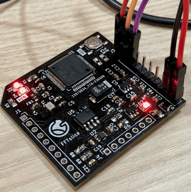
Module evaluating FFT with programmable gain control, filtering, and parallel/serial communication
FFTSlice is an open-source printed circuit board by Pyrograf, from the Pyrograf/FFTSlice repository on GitHub. It is a 2-layer board of 40.6 × 38.1 mm with 61 parts on 80 nets, routed with 566 tracks and 103 vias.
It is built around the SPX3819M5-L-3-3, BZM55C3V3 and PMEG2005EJ. Its parts include 21 capacitors, 9 resistors, 6 diodes, 5 ICs and 3 connectors. It belongs with the STM32 boards of this library.


Module to evaluate FFT. Communication with SPI. PGA for gain control. 2 selectable channels, additional DAC channel for selftest.
See notebook with all calculations.
Frequencies from 20 Hz to 20 kHz are splitted into 100 ranges in logspace to better fit sound perception.
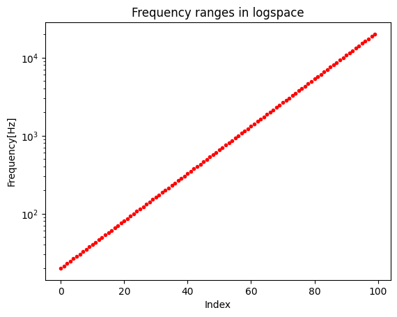
3 variables affects output DAC frequency:
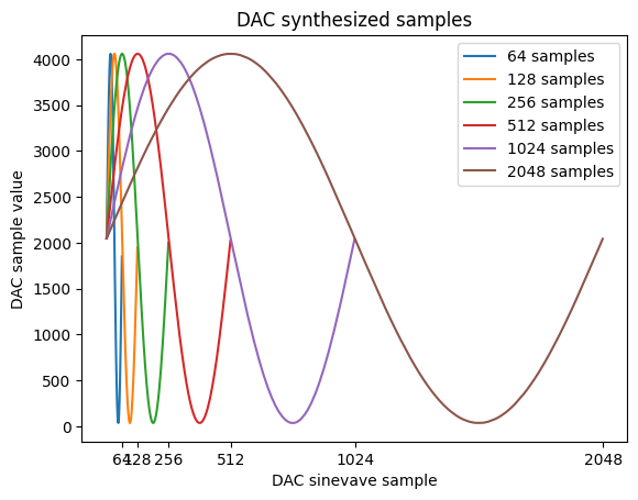
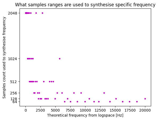
Divider can be freely changed, but samples count have to be generated in advance and stored in FLASH. There are 6 samples counts: 64, 128, 256, 512, 1024 and 2048. Higher samples counts fits better to generate low frequencies, lower samples counts are better fot higher frequencies.
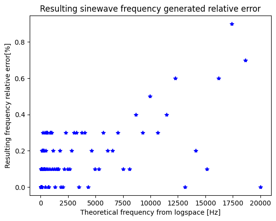
100 parameters are calculated so that samples count and divider lowers time in which output voltage remain the same, and deviation from theoretical frequency is acceptable.
Resulting error remains below 1% as seen in the plot:
Matching of samples counts is more or less proportional:
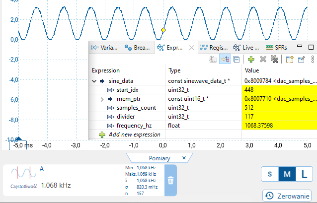
Resulting frequencies are very close to theoretically calculated. In the plot sinewave with output buffer enabled without low pass filter:
| Qty | Value | Footprint | References |
|---|---|---|---|
| 9 | TestPoint | TestPoint:TestPoint_Pad_D1.0mm | TP1, TP2, TP3, TP4, TP5, TP6, TP7, TP8, TP9 |
| 6 | 1uF | Capacitor_SMD:C_0603_1608Metric | C2, C13, C14, C17, C20, C21 |
| 5 | 100nF | Capacitor_SMD:C_0603_1608Metric | C4, C11, C12, C16, C18 |
| 4 | 100k | Resistor_SMD:R_0805_2012Metric_Pad1.20x1.40mm_HandSolder | R6, R7, R8, R9 |
| 4 | 10nF | Capacitor_SMD:C_0603_1608Metric | C1, C10, C15, C19 |
| 4 | 4k7 | Resistor_SMD:R_0805_2012Metric_Pad1.20x1.40mm_HandSolder | R1, R2, R3, R5 |
| 3 | 100nF | Capacitor_SMD:C_0402_1005Metric_Pad0.74x0.62mm_HandSolder | C7, C8, C9 |
| 3 | LED | LED_SMD:LED_0805_2012Metric_Pad1.15x1.40mm_HandSolder | D1, D2, D4 |
| 3 | ~ | Jumper:SolderJumper-2_P1.3mm_Bridged_RoundedPad1.0x1.5mm | JP1, JP2, JP3 |
| 2 | 10pF | Capacitor_SMD:C_0603_1608Metric | C3, C5 |
| 2 | 120R@100MHz | Inductor_SMD:L_0603_1608Metric_Pad1.05x0.95mm_HandSolder | FB1, FB2 |
| 2 | BZM55C3V3 | Diode_SMD:D_MicroMELF | D5, D6 |
| 2 | Conn_01x10 | Connector_PinSocket_2.54mm:PinSocket_1x10_P2.54mm_Vertical | J1, J3 |
| 2 | SPX3819M5-L-3-3 | Package_TO_SOT_SMD:SOT-23-5 | U3, U4 |
| 1 | 100uF | Capacitor_Tantalum_SMD:CP_EIA-6032-15_Kemet-U_Pad2.25x2.35mm_HandSolder | C6 |
| 1 | 16MHz 10pF | Crystal:Crystal_SMD_Abracon_ABM10-4Pin_2.5x2.0mm | Y1 |
| 1 | Conn_01x07 | Connector_PinSocket_2.54mm:PinSocket_1x07_P2.54mm_Vertical | J4 |
| 1 | LOGO | LOGO | G*** |
| 1 | MCP6S22-I_MS | Package_SO:SOP-8_3.9x4.9mm_P1.27mm | U5 |
| 1 | NA | Resistor_SMD:R_0805_2012Metric_Pad1.20x1.40mm_HandSolder | R4 |
| 1 | PMEG2005EJ | Diode_SMD:D_SOD-323F | D3 |
| 1 | RESET | Button_Switch_SMD:SW_SPST_TL3342 | SW1 |
| 1 | STM32G081RBTx | Package_QFP:LQFP-64_10x10mm_P0.5mm | U1 |
| 1 | TS5A9411DCKR | TS5A9411DCKR_footprints:DCK0006A_N | U2 |
It measures 40.6 × 38.1 mm and has 2 copper layers, 1.6 mm thick.
61 parts, built around the SPX3819M5-L-3-3, BZM55C3V3 and PMEG2005EJ. The full list of its parts is on this page, with links to each part's symbol and footprint where PCBKit's library has them.
From the Pyrograf/FFTSlice repository on GitHub, at the commit this page was made from: the board is Board/fft_slice/fft_slice.kicad_pcb and its schematic Board/fft_slice/analog.kicad_sch. PCBKit opens the board in the browser, with nothing to install.
Its repository states no licence, so its author keeps all rights: ask Pyrograf before reusing the design.

adamgmakes/SplitFlapDisplay
A modular, 3D-printed split-flap display controllable over RS485 from a Raspberry Pi. Each module holds 64 characters and modules can be chained together to build a display of any width.


skorokithakis/tiny-ESP8266-breakout
A very small and basic ESP8266 breakout board


gadjet/Window-Door-sensor-Version-5
Version 5 of the Window/Door sensor project this time with ultra low current consumption

sequoia-hope/rp2350-motor-controller
An RP2350 based brushless motor controller

kbob/MinimumViableSynth
A virtual analog synthesizer with lots of knobs and buttons.