2 layers41.3 × 38.1 mm
 adamgmakes/SplitFlapDisplay190
A modular, 3D-printed split-flap display controllable over RS485 from a Raspberry Pi. Each module holds 64 characters and modules can be chained together to build a display of any width.
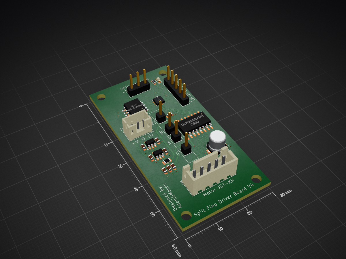
SplitFlapDriverATtiny1616V4 is an open-source printed circuit board by adamgmakes, from the adamgmakes/SplitFlapDisplay repository on GitHub. It is a 2-layer board of 30 × 60 mm with 25 parts on 38 nets, routed with 196 tracks and 22 vias.
It is built around the SN65HVD72DRBR, SPX3819M5-L-3-3 and SPX3819M5-L-5-0, with the ULN2003ADRG among its other parts. Its parts include 9 capacitors, 8 connectors, 5 ICs, 2 resistors and 1 diode. It belongs with the AVR (ATmega, ATtiny) boards of this library.


A modular, 3D-printed split-flap display controllable over RS485 from a Raspberry Pi. Each module holds 64 characters and modules can be chained together to build a display of any width.
YouTube Build Video: https://www.youtube.com/watch?v=-C8_AtxEEQc
Each module contains:
Modules communicate over a shared RS485 bus. A Raspberry Pi running a Python web interface sends commands over USB-RS485 to each module individually by address.
cad/                       - 3D printable parts (Bambu Lab profiles included)
flaps-generator/           - OpenSCAD code to automatically generate (custom) flaps
pcb/
  driver-v2/               - Driver PCB KiCad project used in the video build
  driver-v3/               - Updated driver PCB KiCad project, slightly cheaper to manufacture
  bus-board/               - Bus board KiCad project
  bus-board-5-module/      - 5-module variant of the bus board
firmware/                  - Arduino firmware for the PCBs
frontend/                  - Raspberry Pi Python web frontend
docs/datasheets/           - Component datasheets
BOM.md                     - Bill of materials
OnShape Model: https://cad.onshape.com/documents/87c916b33ca5d6492b457485/w/b3e5f0f05f6619e6e7931347/e/582ef2164e20b0aa994708ab
See BOM.md for the complete bill of materials, broken into three sections:
The driver board is designed to be ordered from JLCPCB with their PCB Assembly (PCBA) service so the SMD components arrive pre-soldered.
pcb/driver-v2/Alternatively, pre-exported Gerber and PCBA files are already be present in the KiCad project folder.
BOM.md match what is in this file.Note: A few through-hole parts (pin headers, JST connectors) are not included in PCBA. These are listed in the BOM and will need to be soldered by hand.
All printable files are in the cad/ folder. A Bambu Lab print profile is included in cad/64FlapsWithLetters (parts and bambu print profile)/ for the flaps. Print the flaps in the correct colour for each character — see the video for details on the full 64-character set.
Parts per module:
If you want to generate your own flaps, with your own font, size and characters, you can use the OpenSCAD script to automatically generate this.
Located in firmware/. The firmware is Arduino-based and targets the ATtiny1616.
Located in frontend/. A Python web interface running on a Raspberry Pi sends display commands over USB-RS485 at 115200 baud.
Need a USB-serial dongle. I used this one: https://www.adafruit.com/product/5994
This project is licensed under Creative Commons Attribution-NonCommercial-ShareAlike 4.0 International (CC BY-NC-SA 4.0).
You are free to share and adapt this project for non-commercial purposes, as long as you give appropriate credit to Adam G Makes and distribute any derivatives under the same license.
| Qty | Value | Footprint | References |
|---|---|---|---|
| 4 | 470n | Capacitor_SMD:C_0603_1608Metric | C2, C3, C6, C8 |
| 4 | Conn_01x01_Pin | Connector_PinHeader_2.54mm:PinHeader_1x01_P2.54mm_Vertical | J2, J6, J7, J8 |
| 3 | 10u | Capacitor_SMD:C_0603_1608Metric | C4, C5, C9 |
| 1 | 0R | Resistor_SMD:R_0805_2012Metric | R1 |
| 1 | 100n | Capacitor_SMD:C_0603_1608Metric | C7 |
| 1 | 100u | Capacitor_SMD:C_Elec_5x5.4 | C1 |
| 1 | 60R | Resistor_SMD:R_0603_1608Metric | R2 |
| 1 | ATtiny1616-MNR | Package_DFN_QFN:VQFN-20-1EP_3x3mm_P0.4mm_EP1.7x1.7mm | U1 |
| 1 | Conn_01x05_Pin | Connector_PinHeader_2.54mm:PinHeader_1x05_P2.54mm_Vertical | J5 |
| 1 | Hall Effect | Connector_JST:JST_PH_B3B-PH-K_1x03_P2.00mm_Vertical | J4 |
| 1 | LED | LED_SMD:LED_0603_1608Metric | D1 |
| 1 | SN65HVD72DR | Package_SO:SOIC-8_5.3x6.2mm_P1.27mm | U3 |
| 1 | SPX3819M5-L-3-3 | Package_TO_SOT_SMD:SOT-23-5 | U5 |
| 1 | SPX3819M5-L-5-0 | Package_TO_SOT_SMD:SOT-23-5 | U6 |
| 1 | Stepper Connector | Connector_JST:JST_XH_B5B-XH-A_1x05_P2.50mm_Vertical | J3 |
| 1 | ULN2003ADR | Package_SO:SOIC-16W_5.3x10.2mm_P1.27mm | U2 |
| 1 | UPDI Programming | Connector_PinHeader_2.54mm:PinHeader_1x03_P2.54mm_Vertical | J1 |
It measures 30 × 60 mm and has 2 copper layers, 1.6 mm thick.
25 parts, built around the SN65HVD72DRBR, SPX3819M5-L-3-3, SPX3819M5-L-5-0 and ULN2003ADRG. The full list of its parts is on this page, with links to each part's symbol and footprint where PCBKit's library has them.
From the adamgmakes/SplitFlapDisplay repository on GitHub, at the commit this page was made from: the board is PCBs/driver-v4/SplitFlapDriverATtiny1616V4.kicad_pcb.kicad_pcb and its schematic PCBs/bus-board/SplitFlapBusBoard.kicad_sch. PCBKit opens the board in the browser, with nothing to install.
Its repository states no licence, so its author keeps all rights: ask adamgmakes before reusing the design.


PinballWizards/pcb_solenoid_board
KiCAD PCB files for Solenoid Node Board
