2 layers71.9 × 98.6 mm
Ark
tmtrcreations/The_Ark
PCB design files and configuration files for a Raspberry Pi CM3L based tablet.
112 parts9MIT

 kbob/MinimumViableSynth28
A virtual analog synthesizer with lots of knobs and buttons.
Io daughterboard is an open-source printed circuit board by kbob, from the kbob/MinimumViableSynth repository on GitHub, published under the GPL-3.0 licence. It is a 2-layer board of 120 × 66 mm with 136 parts on 191 nets, routed with 1,637 tracks and 117 vias.
It is built around the 74HC244D, FAN5333BSX and SN74LV1T34DCKR, with the SPX3819M5-L-3-3, FH12A-40S-0.5SH(55) and MBR0540 among its other parts. Its parts include 35 resistors, 22 connectors, 16 capacitors, 11 ICs and 2 diodes. It belongs with the audio and music boards of this library.


A virtual analog synthesizer with lots of knobs and buttons.
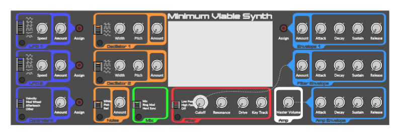
This is a polyphonic, monotimbral, virtual analog synth. The audio engine runs as an Apple Audio Unit on a Macintosh. The control panel, shown here, will provide dedicated controls for most of the synth's functions.
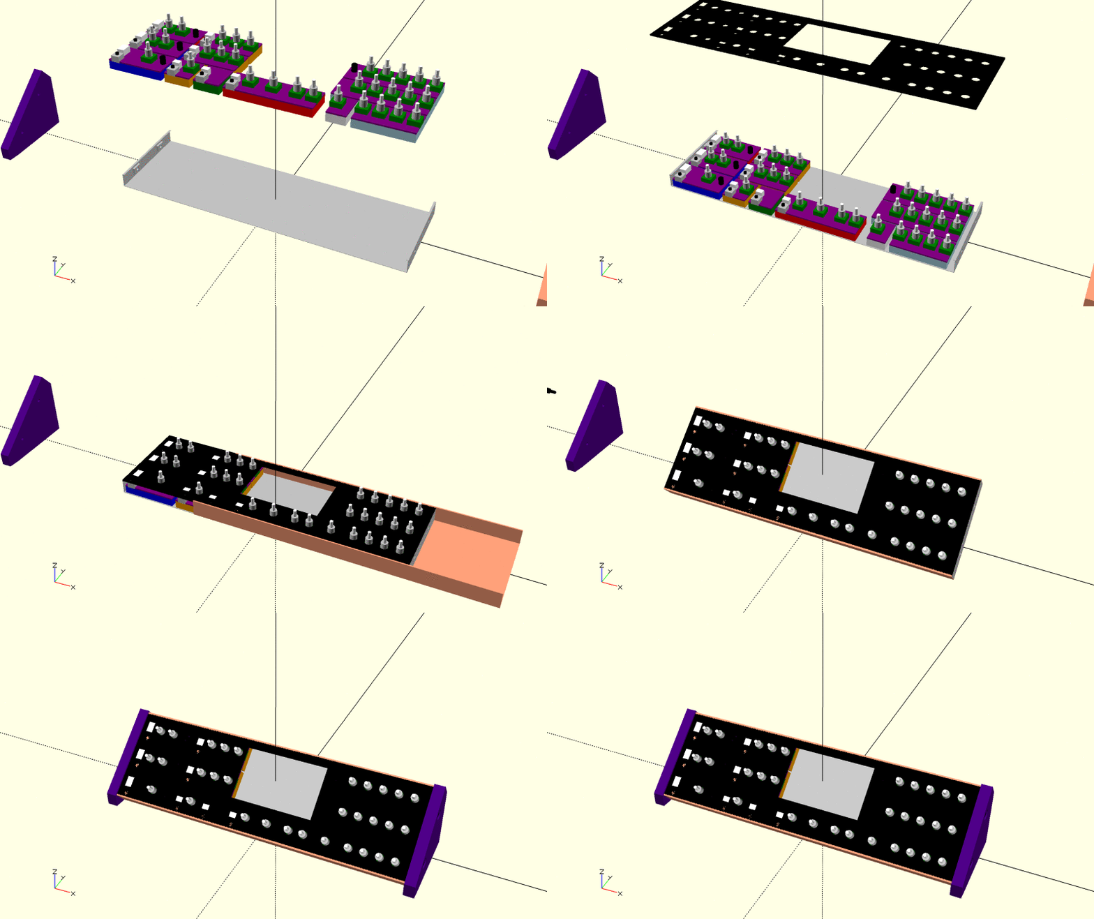
The end goal is a self contained keyboard synth with knobs and buttons with the classic connections: audio out, MIDI in/out, USB MIDI in/out. I am getting there in three phases.
Phase 1 (complete 2015-01-01): Softsynth. The audio engine runs as an Audio Unit on a Mac. It accepts MIDI messages and produces beautiful polyphonic analog sounds. Or gritty, disturbing analog sounds. It plugs in to DAW software (I use Logic Pro X).
Phase 2 (in progress): Knobs and buttons. I am designing and building a front panel (see above) with knobs, buttons, and an LCD touchscreen. The goal is to make it as easy as possible to understand what the synth is doing at any time.
Phase 3 (future): Stand-alone. Build an enclosure that houses a keyboard, the knob and button panel, I/O jacks, and a processor (TBD) that can run the audio engine. I'm looking at FPGAs...
Learn stuff. Music theory, DSP, PCB layout, CAD and machining, more.
Check out synth-notes.txt for my thoughts as I worked things out.
I built 8 slave modules: the LFOs, the Controllers module, the oscillators, the noise source, mixer, and filter. I've since killed the filter module, and one of the oscillators' LED has burnt out its red component. I have parts and tools to repair those; just haven't done it yet.
I have working UI for the knobs and buttons. Specifically, routing between modulators and targets works, complete with lighting effects.
I made an enclosure from aluminum sheet and melamine end blocks, as illustrated above. It is flimsy, though, so that needs to be re-done.
I had the master, slaves, and LCD panel connected via a breadboard. The breadboard wiring got flaky, so I stopped to design a PCB. The PCB snaps onto the back of the Discovery board, It routes video to the LCD touch screen, SPI to the slaves, and serial MIDI to a future MIDI I/O board.
I am currently designing the graphics for the LCD panel.
(Over a year since the last update. Oops.)
Three slave modules have been built. (LFO1, LFO2, Controllers.) All the slave module PCBs are fabricated.
The master-slave communications are working over SPI. The master generates MIDI events. I can push a button on a slave and hear its effect on the audio engine.
I blew up one of the LFO modules, probably with static discharge. I repaired it (swapped in a new Teensy LC), and it works now. It was an ugly repair.
Current tasks:
The audio engine has been stable since January, though it does not exactly match the front panel's feature set.
The front panel was fabricated in July. I used a sheet of acrylic, painted the underside black, then engraved the artwork through the paint with a laser cutter. Then the same laser cutter cut all the holes for the controls. It looks sharp, but not mass produced. I got the work done at InHaus Fabrication.
There is a master microcontroller, an STM32F429, and each module has a slave controller, a Teensy-LC. Each slave directly drives a few knobs, buttons, and LEDs. The master will coordinate all the slaves and provide the MIDI over USB interface. I am currently writing SPI drivers for master-slave communication.
| Qty | Value | Footprint | References |
|---|---|---|---|
| 21 | 10K | Resistors_SMD:R_0603 | R1, R2, R3, R4, R10, R11, R17, R18, R20, R21, R23, R24, R26, R27, R29, R30 +5 |
| 10 | 100nF | Capacitors_SMD:C_0603 | C1, C2, C3, C4, C5, C6, C7, C8, C9, C12 |
| 6 | 74HC244 | Housings_SSOP:TSSOP-20_4.4x6.5mm_Pitch0.65mm | U3, U4, U5, U7, U8, U9 |
| 4 | 100K | Resistors_SMD:R_0603 | R32, R33, R34, R35 |
| 4 | 4K7 | Resistors_SMD:R_0603 | R15, R16, R19, R22 |
| 2 | 100 | Resistors_SMD:R_0603 | R25, R31 |
| 2 | 1M | Resistors_SMD:R_0603 | R14, R28 |
| 2 | 1nF | Capacitors_SMD:C_0603 | C15, C16 |
| 2 | 1µF | Capacitors_SMD:C_0805 | C10, C11 |
| 2 | CONN_02X32 | daughterfeet:Socket_Strip_Reversed_2x32 | P1, P2 |
| 2 | SN74LV1T34DCKR | TO_SOT_Packages_SMD:SOT-23-5 | U10, U11 |
| 1 | 10nF | Capacitors_SMD:C_0603 | C13 |
| 1 | 10µH | Inductors:Inductor_Taiyo-Yuden_NR-60xx | L1 |
| 1 | 1µF | Capacitors_SMD:C_0603 | C14 |
| 1 | 24V | Diodes_SMD:SOD-323 | D2 |
| 1 | 4.3 | Resistors_SMD:R_0603_HandSoldering | R12 |
| 1 | BARREL_JACK | daughterfeet:BARREL_JACK | CON1 |
| 1 | FAN5333BSX | TO_SOT_Packages_SMD:SOT-23-5 | U1 |
| 1 | FH12A-40S-0.5SH | daughterfeet:FH12A-40S | J2 |
| 1 | LOGO | daughterfeet:MVS-logo | G*** |
| 1 | MBR0540 | Diodes_SMD:SOD-123 | D1 |
| 1 | MIDI | Connectors_Molex:Molex_PicoBlade_53047-0410_04x1.25mm_Straight | P19 |
| 1 | N/C | daughterfeet:R_0603_HandSoldering_no_paste | R13 |
| 1 | Reset | daughterfeet:WS-TASV | SW1 |
| 1 | SPX3819M5-L-3-3 | TO_SOT_Packages_SMD:SOT-23-5 | U2 |
| 1 | STMPE811QTR | Housings_DFN_QFN:QFN-16-1EP_3x3mm_Pitch0.5mm | U6 |
| 1 | Slave 1A | daughterfeet:Molex_PicoBlade_53047-0610_06x1.25mm_Straight | P3 |
| 1 | Slave 1B | daughterfeet:Molex_PicoBlade_53047-0610_06x1.25mm_Straight | P7 |
| 1 | Slave 1C | daughterfeet:Molex_PicoBlade_53047-0610_06x1.25mm_Straight | P11 |
| 1 | Slave 1D | daughterfeet:Molex_PicoBlade_53047-0610_06x1.25mm_Straight | P15 |
| 1 | Slave 3A | daughterfeet:Molex_PicoBlade_53047-0610_06x1.25mm_Straight | P4 |
| 1 | Slave 3B | daughterfeet:Molex_PicoBlade_53047-0610_06x1.25mm_Straight | P8 |
| 1 | Slave 3C | daughterfeet:Molex_PicoBlade_53047-0610_06x1.25mm_Straight | P12 |
| 1 | Slave 3D | daughterfeet:Molex_PicoBlade_53047-0610_06x1.25mm_Straight | P16 |
| 1 | Slave 4A | daughterfeet:Molex_PicoBlade_53047-0610_06x1.25mm_Straight | P5 |
| 1 | Slave 4B | daughterfeet:Molex_PicoBlade_53047-0610_06x1.25mm_Straight | P9 |
| 1 | Slave 4C | daughterfeet:Molex_PicoBlade_53047-0610_06x1.25mm_Straight | P13 |
| 1 | Slave 4D | daughterfeet:Molex_PicoBlade_53047-0610_06x1.25mm_Straight | P17 |
| 1 | Slave 5A | daughterfeet:Molex_PicoBlade_53047-0610_06x1.25mm_Straight | P6 |
| 1 | Slave 5B | daughterfeet:Molex_PicoBlade_53047-0610_06x1.25mm_Straight | P10 |
| 1 | Slave 5C | daughterfeet:Molex_PicoBlade_53047-0610_06x1.25mm_Straight | P14 |
| 1 | Slave 5D | daughterfeet:Molex_PicoBlade_53047-0610_06x1.25mm_Straight | P18 |
| 1 | User | daughterfeet:WS-TASV | SW2 |
| 1 | XF2L-0625-1A | daughterfeet:XF2L-0625 | J1 |
The 90 most common of 136 parts.
It measures 120 × 66 mm and has 2 copper layers, 1.6 mm thick.
136 parts, built around the 74HC244D, FAN5333BSX, SN74LV1T34DCKR and SPX3819M5-L-3-3. The full list of its parts is on this page, with links to each part's symbol and footprint where PCBKit's library has them.
From the kbob/MinimumViableSynth repository on GitHub, at the commit this page was made from: the board is ECAD/io_daughterboard/pcb/io_daughterboard.kicad_pcb. PCBKit opens the board in the browser, with nothing to install.
Its repository publishes it under the GPL-3.0 licence: you may reuse it on that licence's terms (keep the author's notice, and for a copyleft licence share your changes alike).
tmtrcreations/The_Ark
PCB design files and configuration files for a Raspberry Pi CM3L based tablet.

nrdsp/rvPhone
The goal of the this project is to develop a privacy enhanced, simple and fully featured mobile phone.

oomlout/oomlout_oomp_project_bot_v_2


jhagmar/keynjector
There are several bad solutions to managing passwords securely, e.g.,

will-tm/gbc-cm4-aio
This project is a drop-in replacement board that fits and Gameboy Color shell and use the same IPS display as used in GBC kits.

