2 layers118.1 × 67.3 mm
FunctiongeneratorMK3PowerControl
pstimpel/waveformgenerator
A waveform generator based on XR2206 and Arduino
42 parts14
 pstimpel/waveformgenerator14
A waveform generator based on XR2206 and Arduino
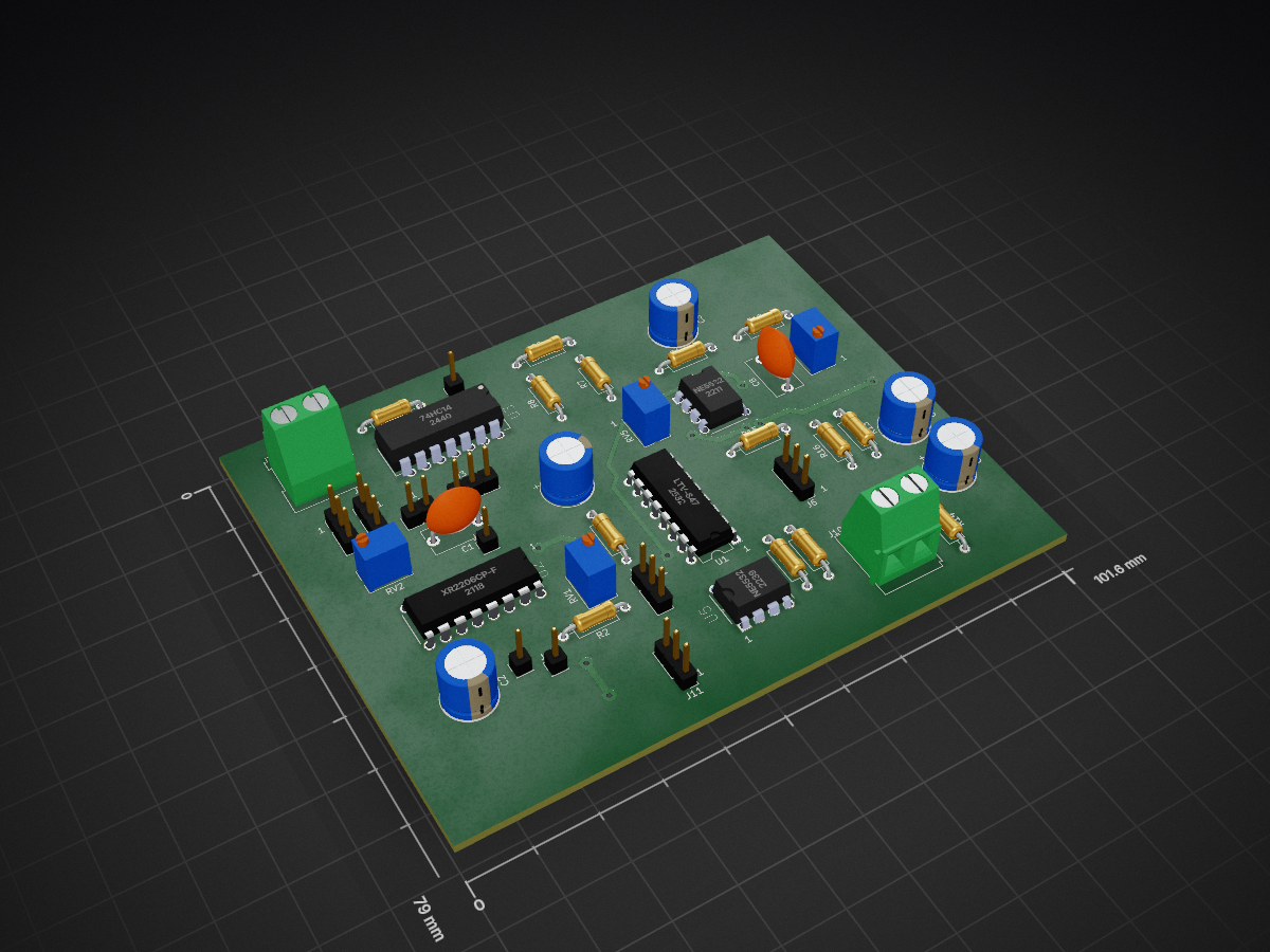
FunctiongeneratorMK3Frequency is an open-source printed circuit board by pstimpel, from the pstimpel/waveformgenerator repository on GitHub. It is a 2-layer board of 101.6 × 79 mm with 43 parts on 45 nets, routed with 515 tracks and 10 vias.
It is built around the NE5532, 74HC14 and LTV-847. Its parts include 14 resistors, 13 connectors, 7 capacitors and 5 ICs.


Click to play video
First of all, the credit for creating the basic circuit goes to Scullcom Hobby Electronics Youtube channel, who is inactive meanwhile - sadly.
https://www.youtube.com/channel/UCDqryeq1kMDSEQwltWqASrA
Project page at Thingiverse: https://www.thingiverse.com/thing:4243526
Project page at Prusaprinters: https://www.prusaprinters.org/prints/27172-xr2206-waveform-generator
Someone said: when starting the hobby electronics, you will need to build 2 things, a power supply and a waveform generator.
I was keen to dive into electronics again, after 20 years of ignoring this hobby. To get some practice again, I thought building such a generator would be fun. It was fun.
Based on Scullcoms circuit I started creating an Arduino controlled waveform gegenerator. My goal was to control as much as possible by the Arduino. So I removed the following parts from the original circuit:
I replaced them with a relay and some opto isolators.
Uh, plenty of challenges.
Figuring out how to replace mechanical switches by opto isolators and relay was kind of a long way for me. First of, I tried to do it by simple transistors, and failed. So opto isolators were the next try, and I was able to replace 3 of 4 switches by these ICs. One left. So I tried a micro relay, and this worked out great.
Another issue I had was to balance out the whole circuit, so I would be able to select halfway decent frequency ranges. Finally, a big enough coarse frequency potentiometer combined with a trim poti did the trick. My goal was to have kind of smooth waveforms, not to hunt Megahertzes for the marketing paper.
I built the whole circuit at least 4 times on breadboards. And what to tell: those breadboards can be a pain in the ass, at least the cheapos.
You will get a waveform generator able to generate sine, triangle and square waves. The frequency range is from about 1 Hz up to 100 kHz, split into 5 ranges you can switch between (1-10, 10-100, 100 to 1,000, 1,000 to 10,000 and 10,000 to 100,000 Hz, roughly). You can adjust the frequency within these ranges by two potis. The amplitude is about +5 to -5 V (adjustable) at the 50 Ohms output, and from 0 to 5V at the TTL output. There is a basic Pulse width modulation available as well. You can adjust the pulse width. By combining sine or triangle waves and PWM you recieve kind of a ramp modulation. The waveform is quite solid, but with 100kHz you will see some distortion and spikes. It seems this is kind of a typical behavior of the XR2206 chipset. There is a frequency counter used to display the set frequency. However, this is kind of an estimation, especially in very low Hz ranges.
This folder contains the stl files to 3D print the enclosure. I was using PLA and my Prusa I3 Mk3 printer. On top, there are 2 PDFs containing labels. You could just print them, cut them out of the sheet of paper, use an exacto knife to cut the holes, and mount it to the front of your enclosure

There are 2 circuits. One keeps all the control stuff and the Arduino, and the other creates the waveform and gets controlled by the control board. There are gerber files, the KICAD board file, and PDFs with the circuit scheme itself. In each subfolder you wil find a list of parts.
Beside the stuff from the parts lists in the circuit folders, you will need
Order PCBs and parts, solder all the stuff together, patch the Arduino using the sketch provided, 3d Print the enclosure, put PCBs inside enclosure, mount LCD, potis and switches to the front, solder dupont style wires to them, connect with the PCBs, mount BNC sockets to the front, use some cable to connect them to the PCB, insert 5.5x2.1 soocket in its pocket, lock it using the lock, connect it to the PCB. Lock the PCBs using the pcblock, secure it using one of the screws. Close the enclosure. Connect power, switch the device on, and have fun.


To run the display you will need to add library LiquidCrystal_I2C by Frank de Brabander.
To have frequence counting, you will need to add library FreqCounter by Martin Nawrath.
I highly recommend testing the circuit on a breadboard before you go for the soldering stuff. You will learn much more that way than by just following this rough guide.

If you look for a decent waveform generator delivering Megahertz samples, buy one.
If you look for the cheapest of all solutions, by such a chinese XR2206 kit for less than 10 USD.
If you want to enjoy DIY, start buying parts and follow the guide I provided. Good luck, wish you well.
'rine 77' https://github.com/rine77 contributed updated circuit data, compatible with Kicad6
This project was finished during the spare time provided by Corona. If someone reads this in the future, I really hope Corona is no issue anymore. Until then: stay safe, wash your hands, and take care of your family.
| Qty | Value | Footprint | References |
|---|---|---|---|
| 6 | 1k | Resistor_THT:R_Axial_DIN0207_L6.3mm_D2.5mm_P10.16mm_Horizontal | R2, R5, R6, R8, R13, R14 |
| 3 | 10k | Resistor_THT:R_Axial_DIN0207_L6.3mm_D2.5mm_P10.16mm_Horizontal | R7, R17, R18 |
| 3 | 20k | Potentiometer_THT:Potentiometer_Bourns_3266Y_Vertical | RV1, RV5, RV6 |
| 2 | 100 | Resistor_THT:R_Axial_DIN0207_L6.3mm_D2.5mm_P10.16mm_Horizontal | R11, R12 |
| 2 | 100pF | Capacitor_THT:C_Disc_D9.0mm_W5.0mm_P7.50mm | C1, C8 |
| 2 | 220uF | Capacitor_THT:CP_Radial_D8.0mm_P5.00mm | C6, C7 |
| 2 | 47k | Resistor_THT:R_Axial_DIN0207_L6.3mm_D2.5mm_P10.16mm_Horizontal | R15, R16 |
| 2 | NE5532 | NE5532P:DIP254P762X508-8 | U4, U5 |
| 1 | 10u | Capacitor_THT:CP_Radial_D8.0mm_P5.00mm | C3 |
| 1 | 10uF | Capacitor_THT:CP_Radial_D8.0mm_P5.00mm | C2 |
| 1 | 12V-GND-5V | Connector_PinHeader_2.54mm:PinHeader_1x03_P2.54mm_Vertical | J3 |
| 1 | 1u | Capacitor_THT:CP_Radial_D8.0mm_P5.00mm | C4 |
| 1 | 2k2 | Resistor_THT:R_Axial_DIN0207_L6.3mm_D2.5mm_P10.16mm_Horizontal | R9 |
| 1 | 50 Ohm OUT | TerminalBlock:TerminalBlock_Altech_AK300-2_P5.00mm | J10 |
| 1 | 50k | Potentiometer_THT:Potentiometer_Bourns_3266Y_Vertical | RV2 |
| 1 | 74HC14 | SN74HC14N:DIP254P762X508-14 | U3 |
| 1 | FreqCoarse 1M | Connector_PinHeader_2.54mm:PinHeader_1x03_P2.54mm_Vertical | J8 |
| 1 | FreqCounterD5 | Connector_PinHeader_2.54mm:PinHeader_1x01_P2.54mm_Vertical | J4 |
| 1 | FreqFine 10k | Connector_PinHeader_2.54mm:PinHeader_1x03_P2.54mm_Vertical | J9 |
| 1 | FreqRange | Connector_PinHeader_2.54mm:PinHeader_1x02_P2.54mm_Vertical | J1 |
| 1 | LTV-847 | Package_DIP:DIP-16_W7.62mm | U1 |
| 1 | MO | Connector_PinHeader_2.54mm:PinHeader_1x01_P2.54mm_Vertical | J13 |
| 1 | OUT Gain 10k | Connector_PinHeader_2.54mm:PinHeader_1x03_P2.54mm_Vertical | J11 |
| 1 | PulseWidth 100k | Connector_PinHeader_2.54mm:PinHeader_1x03_P2.54mm_Vertical | J7 |
| 1 | SIN-TRI-SQU-PWM | Connector_PinHeader_2.54mm:PinHeader_1x03_P2.54mm_Vertical | J6 |
| 1 | TTL OUT | TerminalBlock:TerminalBlock_Altech_AK300-2_P5.00mm | J5 |
| 1 | WaveA1 | Connector_PinHeader_2.54mm:PinHeader_1x01_P2.54mm_Vertical | J2 |
| 1 | WaveA2 | Connector_PinHeader_2.54mm:PinHeader_1x01_P2.54mm_Vertical | J12 |
| 1 | XR2206CP-F | XR2206CP-F:DIP254P762X533-16 | U2 |
It measures 101.6 × 79 mm and has 2 copper layers, 1.6 mm thick.
43 parts, built around the NE5532, 74HC14 and LTV-847. The full list of its parts is on this page, with links to each part's symbol and footprint where PCBKit's library has them.
From the pstimpel/waveformgenerator repository on GitHub, at the commit this page was made from: the board is circuits/frequencygenerator/FunctiongeneratorMK3Frequency.kicad_pcb. PCBKit opens the board in the browser, with nothing to install.
Its repository states no licence, so its author keeps all rights: ask pstimpel before reusing the design.
pstimpel/waveformgenerator
A waveform generator based on XR2206 and Arduino


tnn85/MPCNC-Nano-Estlcam-Shield
Ein CNC Shield für die MPCNC in Verwendung mit Estlcam

ftl/atu100wifi
A wifi adapter device for David Fainitski's ATU-100 antenna tuner (https://github.com/Dfinitski/N7DDC-ATU-100-mini-and-extended-boards)


411568/Atmega8_FM_radio
Simple FM radio based on Atmega8 and TEA5767 module

JhonVelasquez/Embedded_system_Synchronize_Plant
Project of a embedded system that synchronizes signals in a plant. There is electronic (PCB) and software design (FreeRTOS for STM32F7).