Skip to the content
PCBKitNew board
2 layers95.9 × 112.6 mmLab supply, the printed circuit board in 3D

Linear 0-30V, 2A lab supply

Size
95.9 × 112.6 mm
Copper layers
2
Thickness
1.6 mm
Parts
90
Nets
75
Pads
267
Tracks, vias
651, 17
Pours
1
Routed
Yes
KiCad
KiCad 7 (file 20221018)
Created
20 Oct 2023
Updated
12 May 2024

Overview

Lab supply is an open-source printed circuit board by prydin, from the prydin/lab-supply repository on GitHub. It is a 2-layer board of 95.9 × 112.6 mm with 90 parts on 75 nets, routed with 651 tracks and 17 vias.

It is built around the LM324, MCP3202-CI/P and MCP4922-E/P, with the SB140, 1N4752A and BD139 among its other parts. Its parts include 30 resistors, 21 capacitors, 10 diodes, 8 ICs and 4 transistors. It belongs with the power boards of this library.

Main components

7

README

README.md

Linear 0-30V, 2A lab power supply
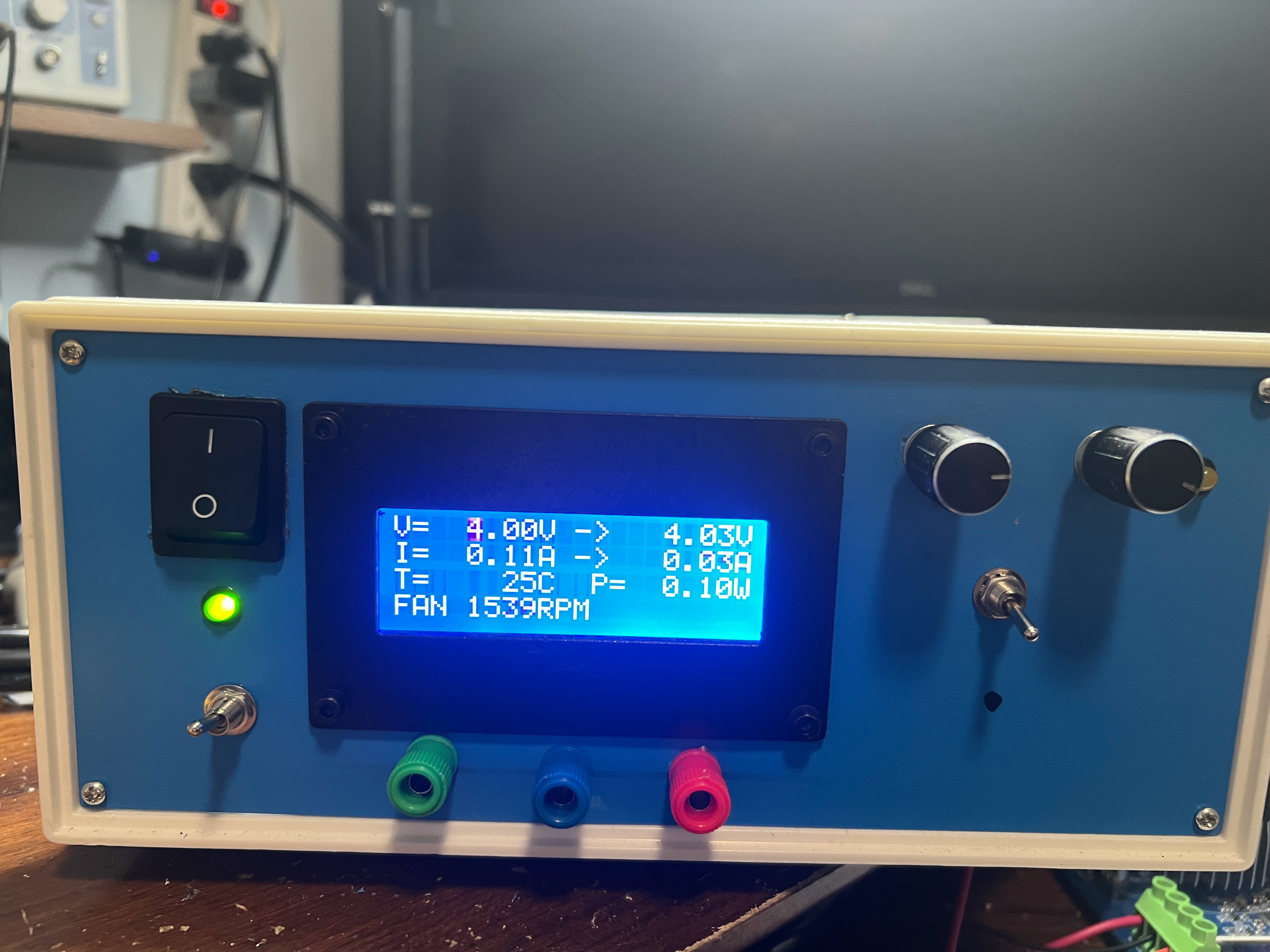
3d rendering

Disclaimer

This supply has been built and tested and does work. However, I am a hobbyist doing this to learn. You are welcome to follow along, but keep the experimental status in mind and always exercise caution when dealing with electricity!

Abstract

This project aims to design a high-performance, high-stability microcontroller-based lab power supply. I am mostly doing this to learn, but also because I'm tired of cheap switchmode power supplies delivering power riddled with RF noise.

Principle of operation

High voltage section

The high voltage section is very simple and consists of a regular AC inlet with a safety capacitor across it. There is a 3A fuse in series with the hot lead and a two pole mains switch. The transformer is a 24V/4A unit with a 12V center tap. Once rectified, the voltage reaches about 36V at my location. Mains ground is connected to the chassis as well as the ground output terminal.

Analog secion

32-36V AC enters the circuit at the AC1 and AC2 terminals and gets rectified and smoothed into approximately 36-40V DC. This voltage is then pre-regulated down to 32V through Q3 which is gets its voltage reference the backwards bias of D3. This voltage is used to power the opamps. The CNT input is the transformer center tap, which should be around 15V and is used to create the +12V and +5V voltages.

The U1D opamp acts as a voltage regulation amplifier and expects a control voltage between 0-4.096V on its postive input. The feedback loop is tuned to 7.32x amplification, resulting in an output voltage ranging from 0-30V. The Darlington pair at Q3 acts as a emitter follower current amplifier.

Current regulation is based on a high-side current sensing resistor, R27. The differential voltage across the current sense resistor is amplified to a 0-2.5V signal using an INA225 current sense amplifier. This voltage is then sent to the positivie input of U1A. The control circuitry feeds a 0-4.096V signal to the V_ISET input, which is scaled down to 0-2.5V through a resistor network. This voltage is then fed to the negative input of U1A. When the voltage from the current sense amplifier goes above the control voltage on the negative input, the opamp will source current to Q2, which brings the base on Q3 low until the current is limited to the set value. Q3 is needed since we want to keep R24 relatively low to avoid voltage drop at high output currents, while making sure U1A isn't sourcing or sinking too much current. Q1 acts as a simple switch for turning on the current limit indicator LED.

Digital section

The digital section is based on a Adafruit ItsyBitsy 5V, which is essentially an Atmel ATMega 32u4 with some support circuitry. This was chosen to simplify the design and keep everything as through hole. The digital section is responsible for feeding the V_VSET and V_ISET voltages to the the analog section, as well as measuring and presenting actual voltages and currents.

A key component is the LMZ4040DBZ voltage reference, which provides a stable 4.096V reference used by the rest of the circuit.

The control voltages are generated by an MPC4922 12-bit DAC and fed directly to the analog section. The user sets the desired voltage and current using two rotary encoders which can be pushed to switch between a "fine" and "coarse" mode.

The output voltage of the supply is measured by an MCP3202 ADC through a voltage divider network to bring the voltage down to 0-4.096V. Further overvoltage protection is offered by the D12 clamping diode. Current is measured in a similar way, but since that signal is in the 0-1V range, it is first amplified 4.096x by U1B. This signal is also clamped to the 4.096V reference through D10.
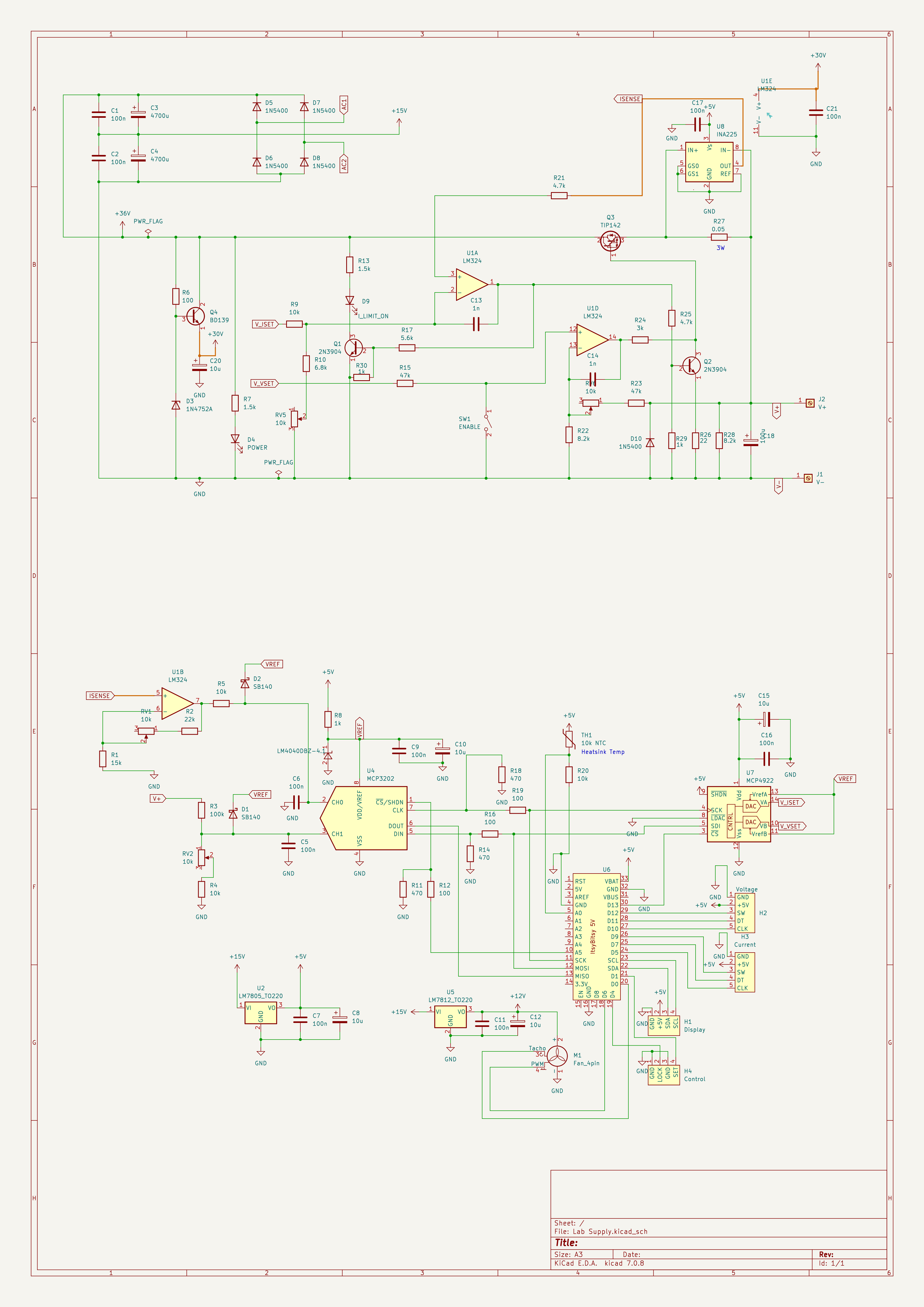
schematic

Controls

Current and voltage

Current and voltage are controlled using two rotary encoders. Pressing the knob switches between coarse and fine mode. In coarse mode, a blinking cursor will indicate the least significant digit subject to change by turning the knob.

Enable/disable

The enable switch enables or disables the output. Notice that this is a "soft" disable that's simply shorting the posisitive terminal on the voltage regulation opamp to ground. Thus, the output is NOT electrically isolated from the rest of the circuit.

Lock mode

When the lock switch is activated, voltage and current output are locked to their current values. The user can still change the settings, but they are not acted upon. When the switch is flipped, the voltage and current output is changed to the current setting. This is useful when a user is carefully dialing in new settings without changing the output while turning the knobs. When locked mode is activated, the "->" symbol between set and actual values on the display is changed to "LCK".

Grounding

This power supply is designed to be floating, i.e. it is isolated from ground. If the user needs either output (plus or minus) to be grounded, they may simply short it to ground using a ground bar or patch wire. Since the supply uses high side current sense, accidental shorts to ground should not cause damage.

Physical design and enclosure

PCB design

This is my very first PCB design and there are many beginners mistakes present in the design. However, it does work. If I ever redesign this, I would make the +36V path shorter, for example. There are also some questionable component placements. As with any open source project, you are encouraged to improve on it! internals
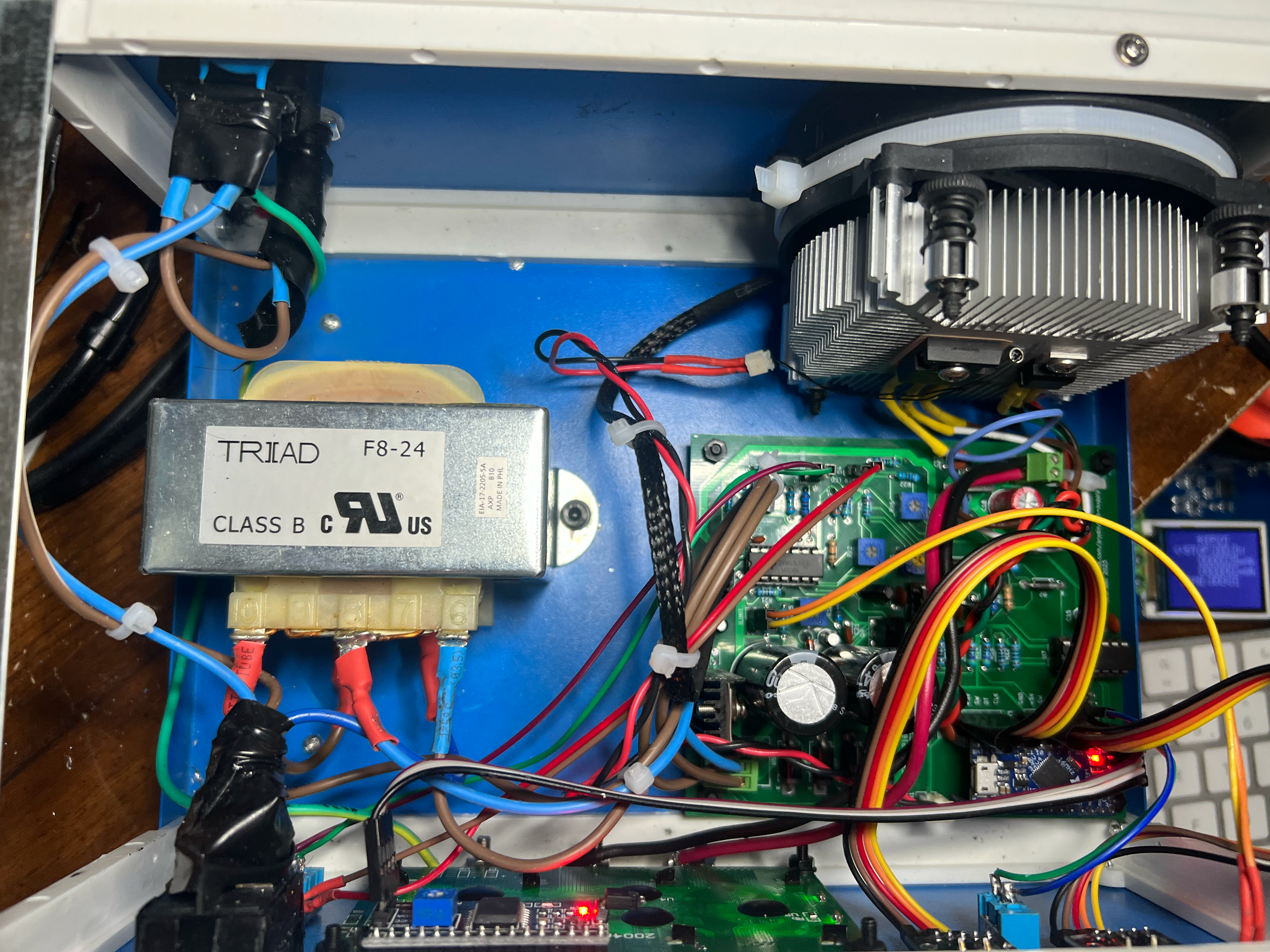
Enclosure

I opted for a cheap sheet metal/plastic box that is widely available on sites like Ali Express and Amazon. It works well, but the metal is fairly thin and tends to flex when unplugging the leads. enclosure

Cooling

The TIP142 output transistor requires good cooling. I opted for a simple $9 AMD CPU cooler and bolted the transistor and the 7805 regulator to it. I'm currently using isolating pads for the TIP142, but I'm not entirely happy with the heat transfer. I might remove that, although I'm not sure I like to have unregulated 36V exposed inside the case. The fan is PWM controlled using a simple temperature curve algorithm. cooling
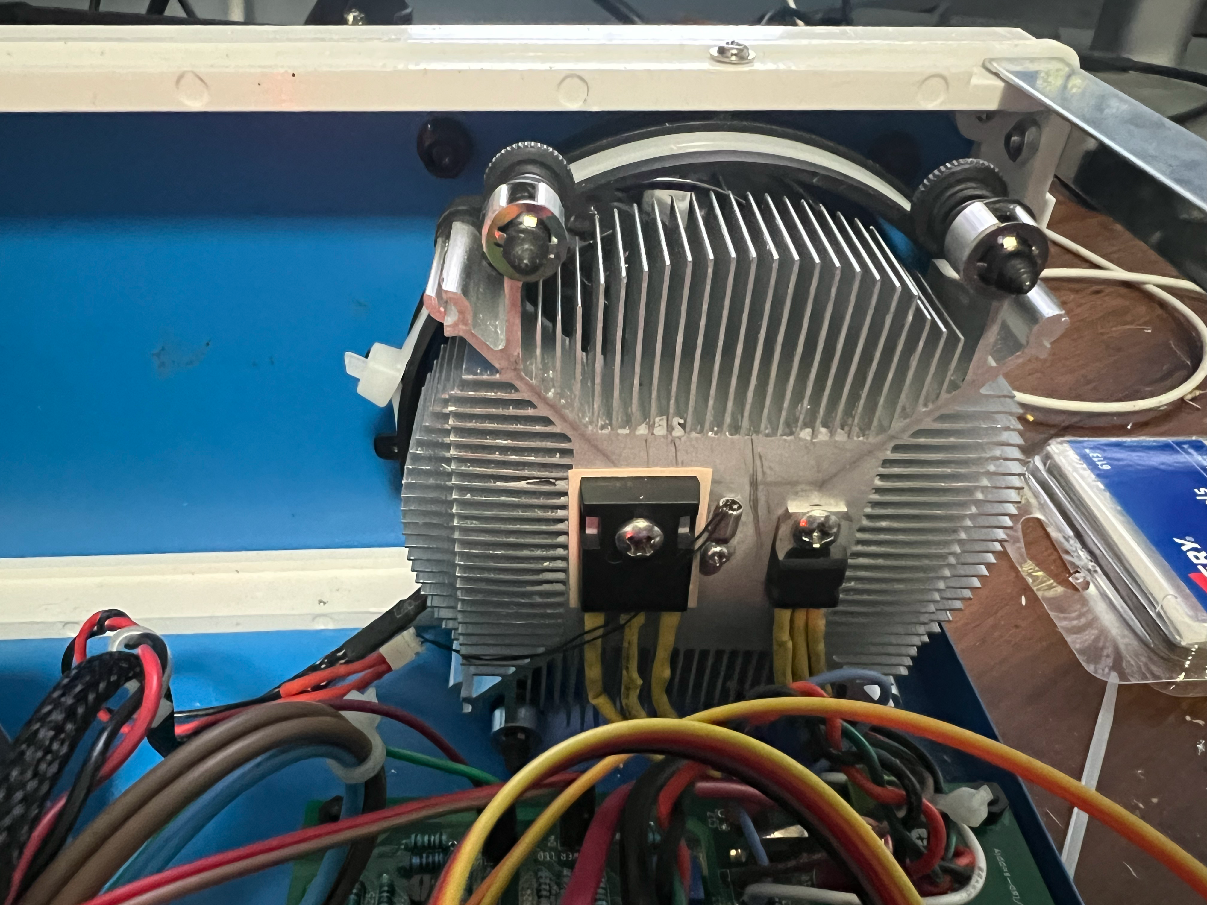
Rotary encoders and switches

The rotary encoders and switches (with exception of the mains switch) are all cheap Amazon products and work well so far.

Parts

90
QtyValueFootprintReferences
11100nCapacitor_THT:C_Disc_D3.4mm_W2.1mm_P2.50mmC1, C2, C5, C6, C7, C9, C11, C16, C17, C19, C21
710kResistor_THT:R_Axial_DIN0204_L3.6mm_D1.6mm_P7.62mm_HorizontalR1, R4, R5, R9, R17, R20, R25
510uCapacitor_THT:CP_Radial_D4.0mm_P1.50mmC8, C10, C12, C15, C20
51N5400Diode_THT:D_DO-201AD_P12.70mm_HorizontalD5, D6, D7, D8, D10
4100Resistor_THT:R_Axial_DIN0204_L3.6mm_D1.6mm_P7.62mm_HorizontalR6, R12, R16, R19
310kPotentiometer_THT:TRIM_3362P-1-253LFRV2, RV5, RV6
31kResistor_THT:R_Axial_DIN0204_L3.6mm_D1.6mm_P7.62mm_HorizontalR8, R29, R30
3470Resistor_THT:R_Axial_DIN0204_L3.6mm_D1.6mm_P7.62mm_HorizontalR11, R14, R18
21.5kResistor_THT:R_Axial_DIN0204_L3.6mm_D1.6mm_P7.62mm_HorizontalR7, R13
21nCapacitor_THT:C_Disc_D3.4mm_W2.1mm_P2.50mmC13, C14
22N3904Package_TO_SOT_THT:TO-92_InlineQ1, Q2
24700uCapacitor_THT:CP_Radial_D18.0mm_P7.50mmC3, C4
247kResistor_THT:R_Axial_DIN0204_L3.6mm_D1.6mm_P7.62mm_HorizontalR15, R23
28.2kResistor_THT:R_Axial_DIN0204_L3.6mm_D1.6mm_P7.62mm_HorizontalR22, R28
2SB140Diode_THT:D_DO-41_SOD81_P10.16mm_HorizontalD1, D2
10.05Resistor_THT:R_Axial_DIN0207_L6.3mm_D2.5mm_P10.16mm_HorizontalR27
1100kResistor_THT:R_Axial_DIN0204_L3.6mm_D1.6mm_P7.62mm_HorizontalR3
1100uCapacitor_THT:CP_Radial_D8.0mm_P3.50mmC18
110k NTCConnector_PinHeader_2.54mm:PinHeader_1x02_P2.54mm_VerticalTH1
11N4752ADiode_THT:D_DO-41_SOD81_P5.08mm_Vertical_KathodeUpD3
120kPotentiometer_THT:TRIM_3362P-1-253LFRV1
1220Resistor_THT:R_Axial_DIN0204_L3.6mm_D1.6mm_P7.62mm_HorizontalR26
122kResistor_THT:R_Axial_DIN0204_L3.6mm_D1.6mm_P7.62mm_HorizontalR2
13kResistor_THT:R_Axial_DIN0204_L3.6mm_D1.6mm_P7.62mm_HorizontalR24
14.7kResistor_THT:R_Axial_DIN0204_L3.6mm_D1.6mm_P7.62mm_HorizontalR21
16.8kResistor_THT:R_Axial_DIN0204_L3.6mm_D1.6mm_P7.62mm_HorizontalR10
1BD139Package_TO_SOT_THT:TO-126-3_VerticalQ4
1ControlConnector_PinHeader_2.54mm:PinHeader_1x04_P2.54mm_VerticalH4
1CurrentConnector_PinHeader_2.54mm:PinHeader_1x05_P2.54mm_VerticalH3
1DisplayConnector_PinHeader_2.54mm:PinHeader_1x04_P2.54mm_VerticalH1
1ENABLEConnector_PinHeader_2.54mm:PinHeader_1x02_P2.54mm_VerticalSW1
1Fan_4pinConnector_Molex:Molex_KK-254_AE-6410-04A_1x04_P2.54mm_VerticalM1
1INA225Package_SO:VSSOP-8_3.0x3.0mm_P0.65mmU8
1INPUTTerminalBlock_4Ucon:TerminalBlock_4Ucon_1x03_P3.50mm_VerticalJ1
1I_LIMIT_ONConnector_PinHeader_2.54mm:PinHeader_1x02_P2.54mm_VerticalD9
1LM324Package_DIP:DIP-14_W7.62mmU1
1LM4040DBZ-4.1Package_TO_SOT_THT:TO-92_HandSolderU3
1LM7805_TO220Package_TO_SOT_THT:TO-220-3_VerticalU2
1LM7812_TO220Package_TO_SOT_THT:TO-220-3_VerticalU5
1MCP3202Package_DIP:DIP-8_W7.62mmU4
1MCP4922Package_DIP:DIP-14_W7.62mmU7
1MountingHole_3.2mm_M3MountingHole:MountingHole_3.2mm_M3
1OUTPUTTerminalBlock_4Ucon:TerminalBlock_4Ucon_1x02_P3.50mm_HorizontalJ4
1POWERConnector_PinHeader_2.54mm:PinHeader_1x02_P2.54mm_VerticalD4
1TIP121Package_TO_SOT_THT:TO-220-3_VerticalQ3
1VoltageConnector_PinHeader_2.54mm:PinHeader_1x05_P2.54mm_VerticalH2
1~Arduino:Itsy Bitsy 5VU6

The 87 most common of 90 parts.

Questions

How big is the Lab supply PCB?

It measures 95.9 × 112.6 mm and has 2 copper layers, 1.6 mm thick.

What parts does the Lab supply use?

90 parts, built around the LM324, MCP3202-CI/P, MCP4922-E/P and SB140. The full list of its parts is on this page, with links to each part's symbol and footprint where PCBKit's library has them.

Where can I download the Lab supply KiCad files?

From the prydin/lab-supply repository on GitHub, at the commit this page was made from: the board is Lab Supply.kicad_pcb and its schematic Lab Supply.kicad_sch. PCBKit opens the board in the browser, with nothing to install.

Can I use the Lab supply design in my own project?

Its repository states no licence, so its author keeps all rights: ask prydin before reusing the design.

Similar boards

  • 2 layers162.8 × 99.9 mmPSU, the printed circuit board in 3D

    PSU

    Sakib-Ansari/Linear_Programmable_Power_Supply

    This repository contains the complete KiCad project for a multi-board linear programmable bench power supply. The design is organized into separate PCBs, including the Power Board, Control Board, Front Panel, Output…

    133 partsMIT
  • 2 layers240 × 63 mmPowerampC300, the printed circuit board in 3D

    PowerampC300

    profdc9/PowerAmpAudio

    Power Amplifier based on Michael Chua's C300 amplifier

    128 parts25
  • 2 layers94 × 70 mmDCDC Buck, the printed circuit board in 3D

    DCDC Buck

    ykupas/DCDC-Buck-KiCAD

    DC-DC buck converter KiCAD project using OpAmps to compensate and control switching. KiCAD v10 used.

    63 parts1MIT
  • 2 layers75 × 50 mmAire apollo, the printed circuit board in 3D

    Aire apollo

    makespacemadrid/ApolloVentilator

    Nos gustaría ser el Marlin de los ventiladores :)

    37 parts6GPL-3.0
  • 2 layers96.6 × 100 mmQuadRaptor, the printed circuit board in 3D

    QuadRaptor

    abdosalem490/QuadRaptor

    148 parts2MIT
  • 2 layers81.2 × 82.6 mmModel train cdu, the printed circuit board in 3D

    Model train cdu

    cbrake/hardware-projects

    Misc hardware projects

    20 parts
  • 2 layers65 × 56.5 mmFlowerweb hat, the printed circuit board in 3D

    Flowerweb hat

    versarite/Flowerweb

    Remote flower watering system with raspberry pi over tailscale net

    18 parts
  • 4 layers100 × 60 mmPocKETlab, the printed circuit board in 3D

    PocKETlab

    bublinak/PocKETlab

    127 partsMIT