
2 layers62.2 × 57.2 mm
ExtCard
profdc9/ISACard
A ISA card for PC/XT/AT that has SD storage and SPI/I2C interfaces using a ATMEGA328P
36 parts46
 profdc9/ISACard46
A ISA card for PC/XT/AT that has SD storage and SPI/I2C interfaces using a ATMEGA328P
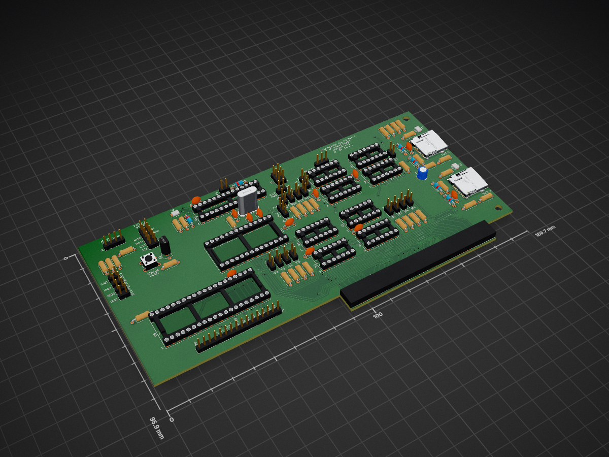
ISACard is an open-source printed circuit board by profdc9, from the profdc9/ISACard repository on GitHub. It is a 2-layer board of 189.7 × 95.9 mm with 101 parts on 167 nets, routed with 1,859 tracks and 124 vias.
It is built around the ATMEGA328P-PU, 74LS32SC and 74LS86. Its parts include 34 resistors, 13 capacitors, 13 ICs, 9 diodes and 5 connectors. It belongs with the interfaces and adapters boards and the AVR (ATmega, ATtiny) boards of this library.


This is a simple card that provides two SD cards as mass storage devices on PC compatibles in an ISA slot. This design is an adaptation of the Apple II version of the card (https://www.github.com/profdc9/Apple2Card). For building in the future, it is designed to use only the most common chips: 74HCT32, 74HCT86, 28C64B/27C128/28C256, 82C55A, and ATMEGA328P. It does not use Compactflash format as that is a rather uncommon memory card format at the time of this writing (Oct 2025). The SD card interface is not as fast as a Compactflash card, however, being read through SPI. Hopefully, the components to build this board will be available for many years to come to retro enthusiasts.
There is also a 10 pin SPI port to connect an external Wiznet 5500 Ethernet port. A simple packet driver is written to interface this to the MSDOS TCP/IP stacks as described below.
The Arduino firmware (in the ISA2Arduino directory) communicates through the 8255 bidirectional parallel port to the ISA bus. It can expose a SD card either as a single raw block device, or it can use an image file on a FAT16/32 filesystem on the SD card as the block device. Block device image files are named BLKDEVXX.IMG where XX is a hexadecimal number between 01h and 0FFh denoting the file number. The default (and fallback) is to use BLKDEV01.IMG on the SD card in SLOT 1 if it is formatted for a FAT FS. There is a MSDOS COM file called "SETBLKDV" that sets the block device number to both SD slots, with the format being:
SETBLKDV <I/O address in hex> <block device number slot 1 in hex> <block device number slot 2 in hex>.For example, to set the block device to 02h on slot 1 and 0Ch on slot 2, with the card being at I/O address 0330h:
SETBLKDV 330 02 0CBlock device number 00h is reserved for exposing the entire SD card as a raw block device (partition table and everything) to the host. If you do not intend for the entire card to be usable and modifiable by the host, then do not choose this option. Most modern SD cards have a very large capacity as compared to what MSDOS is designed to handle. SD cards with up to 8.4 GB capacity can be accommodated by C/H/S addressing using 255 heads and 63 sectors, but larger cards can be accommodated only by LBA. Therefore larger cards are likely only to be usable by FreeDOS or another operating system designed to handle that case.
The BIOS on the card is a modified version of the XT IDE Universal BIOS with a driver added for the SD card device. It must be configured using the xtidecfg.com program as is required by other versions of the XT IDE Universal BIOS. As a bonus, you get the other features of the XT IDE Universal BIOS as well, and it should support the other IDE devices already in the BIOS. The card supports up to a 32 KB ROM, with the jumpers enabling 8K, 16K, or 32K ROM sizes. Read only and writing may also be enabled for the EEPROM so that the flash utility may work.
As with other ISA cards that use a BIOS expansion ROM (https://minuszerodegrees.net/rom/misc/ROM%20-%20BIOS%20expansion%20ROM.jpg), a model IBM 5150 (original IBM PC) must have a 10/27/82 dated revision of the motherboard BIOS (https://minuszerodegrees.net/5150/bios/5150_bios_revisions.htm), or a Compaq Portable must have at least revision C of the motherboard BIOS.
The jumpers to set the BIOS location are labeled M13 to M17 on the board so that the ROM may be located to any 8k address in the upper 0C0000h to 0FFFFFh address space. A shorted jumpered location indicates a zero bit, and an open jumper location is a one bit. For example, address 0D0000h (the most common XT IDE Universal BIOS address) is M17, M15, M14, M13 shorted, and M16 open. Two jumpers enable the M13 and M14 address lines to be ignored so that a larger ROM may be used. Similarly, the IO address is marked IO2 to IO9, which may be located at any multiple of four between 000h and 3FCh. For the default address 330h, the jumpers are set to: IO7, IO6, IO3, IO2 shorted, IO9, IO8, IO5, IO4 open. JP17 sets the ROM size to be 32K or 8K/16K, and JP19 sets the ROM size to be 8K or 16K. JP18 sets the ROM to be read only or ready to be flashed.
There is an ICSP connect that may be used to flash the ATMEGA328P in situ. Make sure any SD cards are removed from the slots before flashing! JP10 must be jumpered to power the board with the programmer.
JP9 shorts out a diode that drops the voltage on the ATMEGA328P. Usually JP9 should be present but may be removed if there are problems with some SD cards. J4 is a debugging connector, and J3 is a connector intended to go to a Wiznet 5500 ethernet module through a 10 position IDC cable.
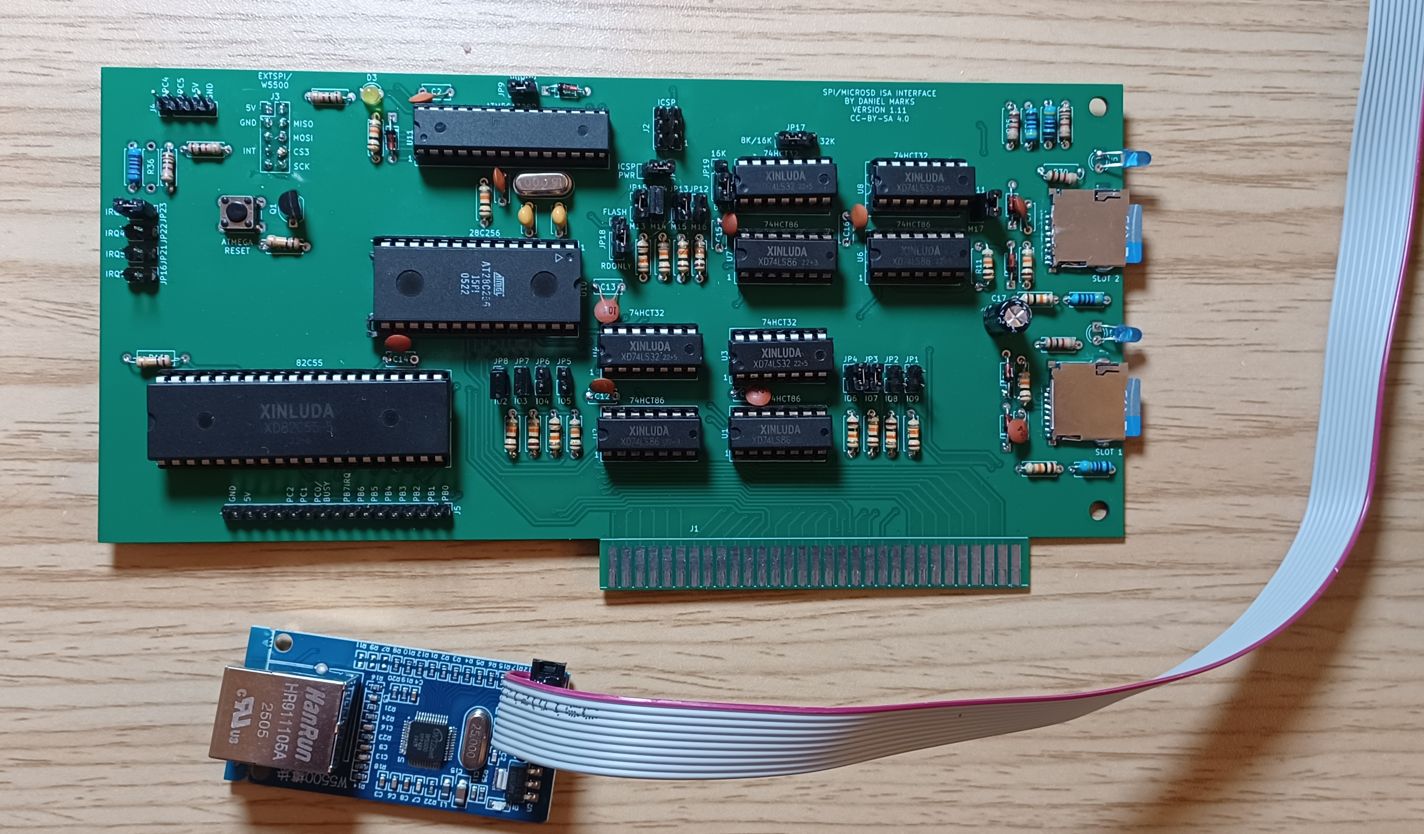
A common Wiznet W5500 adapter board can be connected to the PC card using a 10 pin IDC ribbon cable. A photograph of this board is shown below. This adapter board has a 10 pin header on it with a pinout that corresponds to a 10 pin header marked "EXTSPI/W5500" on the card. A 10 pin IDC ribbon cable may be used to connect the two boards. A DOS Ethernet packet driver has been written to allow a TCP/IP stack such as MTCP (https://www.brutman.com/mTCP/) to be used in MSDOS which this driver has been tested with. This packet driver has the following invocation:
ISA5500 <Software IRQ> <Hardware IRQ> <I/O Address>.For example, with a software IRQ of 0x60, hardware IRQ of 3, and an I/O address of 0x330, the invocation command is:
ISA5500 0x60 3 0x330Because the ethernet and SD card share the same microcontroller, they can not be used simultaneously, and the drivers take turns between mass storage calls and ethernet calls. In order to assemble the packet driver into a COM executable, you will need an assembler like Microsoft or Turbo assembler, and the assemble source files from the packet driver distribution (PKTD11A.ZIP PKTD11B.ZIP PKTD11C.ZIP) (http://crynwr.com/drivers/). You also need to add this to the Makefile:
isa5500.com: head.obj isa5500.obj tail.obj
	$(LINK) head isa5500 tail,isa5500/m;
	exe2com isa5500
	del isa5500.exe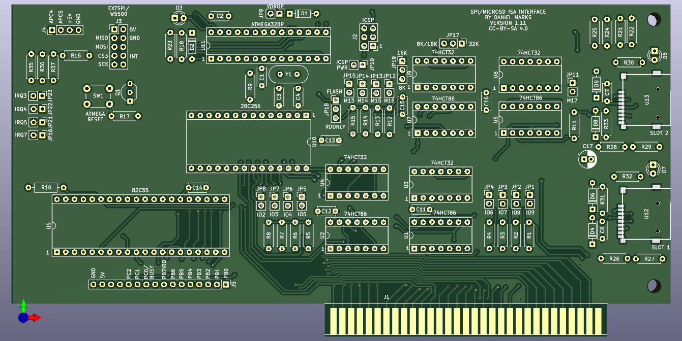
The software derived from the GNU General Public License 2.0 (XT IDE Universal BIOS) is likewise licensed under the GNU General Public License 2.0 as required by the license with the modified source code being publically made available here on the GitHub. Often software written by me is licensed under the zlib license.
The schematic designs (but not the circuit design itself) and the PCB layouts are copyrighted according to the Creative Commons 4.0 Attribution Share-Alike license.
None of these licenses should prevent anyone who wishes to reproduce this hardware and software and sell it from doing so, even for a profit. However, source code modifications to the GPL licensed code must be made available with the product and likewise licensed under the GPLv2.
| Qty | Value | Footprint | References |
|---|---|---|---|
| 19 | 10k | Resistor_THT:R_Axial_DIN0207_L6.3mm_D2.5mm_P7.62mm_Horizontal | R1, R2, R3, R4, R5, R6, R11, R12, R13, R14, R15, R18, R26, R28, R31, R33 +3 |
| 10 | 100 nF | Capacitor_THT:C_Disc_D5.0mm_W2.5mm_P5.00mm | C1, C2, C6, C7, C11, C12, C13, C14, C15, C16 |
| 7 | 1k | Resistor_THT:R_Axial_DIN0207_L6.3mm_D2.5mm_P7.62mm_Horizontal | R16, R22, R23, R25, R30, R32, R37 |
| 6 | 1N4148 | Diode_THT:D_DO-35_SOD27_P7.62mm_Horizontal | D1, D2, D4, D6, D8, D9 |
| 4 | 74LS32 | Package_DIP:DIP-14_W7.62mm_Socket | U3, U4, U8, U9 |
| 4 | 74LS86 | Package_DIP:DIP-14_W7.62mm_Socket | U1, U2, U6, U7 |
| 4 | JP | Connector_PinHeader_2.54mm:PinHeader_1x02_P2.54mm_Vertical | JP16, JP21, JP22, JP23 |
| 3 | Jumper_3_Open | Connector_PinHeader_2.54mm:PinHeader_1x03_P2.54mm_Vertical | JP17, JP18, JP19 |
| 3 | LED | LED_THT:LED_D3.0mm | D3, D5, D7 |
| 2 | 20 pF | Capacitor_THT:C_Disc_D5.0mm_W2.5mm_P5.00mm | C3, C4 |
| 2 | 470R | Resistor_THT:R_Axial_DIN0207_L6.3mm_D2.5mm_P7.62mm_Horizontal | R21, R24 |
| 2 | 4k7 | Resistor_THT:R_Axial_DIN0207_L6.3mm_D2.5mm_P7.62mm_Horizontal | R27, R29 |
| 2 | A2 | Connector_PinHeader_2.54mm:PinHeader_1x02_P2.54mm_Vertical | JP3, JP11 |
| 2 | A3 | Connector_PinHeader_2.54mm:PinHeader_1x02_P2.54mm_Vertical | JP4, JP12 |
| 2 | A4 | Connector_PinHeader_2.54mm:PinHeader_1x02_P2.54mm_Vertical | JP5, JP13 |
| 2 | A5 | Connector_PinHeader_2.54mm:PinHeader_1x02_P2.54mm_Vertical | JP6, JP14 |
| 2 | A6 | Connector_PinHeader_2.54mm:PinHeader_1x02_P2.54mm_Vertical | JP7, JP15 |
| 2 | MicroSD_SPI_CD | ISACard:GCT-MEM2055-00-190-01-A | U12, U13 |
| 2 | MountingHole | MountingHole:MountingHole_3.7mm | H1, H2 |
| 2 | PWR | Connector_PinHeader_2.54mm:PinHeader_1x02_P2.54mm_Vertical | JP9, JP10 |
| 1 | 10 uF | Capacitor_THT:CP_Radial_D5.0mm_P2.00mm | C17 |
| 1 | 100k | Resistor_THT:R_Axial_DIN0207_L6.3mm_D2.5mm_P10.16mm_Horizontal | R10 |
| 1 | 100k | Resistor_THT:R_Axial_DIN0207_L6.3mm_D2.5mm_P7.62mm_Horizontal | R17 |
| 1 | 16 MHz | Crystal:Crystal_HC49-U_Vertical | Y1 |
| 1 | 22k | Resistor_THT:R_Axial_DIN0207_L6.3mm_D2.5mm_P7.62mm_Horizontal | R35 |
| 1 | 28C256 | Package_DIP:DIP-28_W15.24mm_Socket | U10 |
| 1 | 2N3904 | Package_TO_SOT_THT:TO-92_Inline_Wide | Q1 |
| 1 | 82C55A | Package_DIP:DIP-40_W15.24mm_Socket | U5 |
| 1 | A0 | Connector_PinHeader_2.54mm:PinHeader_1x02_P2.54mm_Vertical | JP1 |
| 1 | A1 | Connector_PinHeader_2.54mm:PinHeader_1x02_P2.54mm_Vertical | JP2 |
| 1 | A7 | Connector_PinHeader_2.54mm:PinHeader_1x02_P2.54mm_Vertical | JP8 |
| 1 | ATmega328P-P | Package_DIP:DIP-28_W7.62mm_Socket | U11 |
| 1 | Bus_ISA_8bit | ISACard:BUS_ISA8 | J1 |
| 1 | Conn_01x04 | Connector_PinHeader_2.54mm:PinHeader_1x04_P2.54mm_Vertical | J4 |
| 1 | Conn_01x16 | Connector_PinHeader_2.54mm:PinHeader_1x16_P2.54mm_Vertical | J5 |
| 1 | EXTSPI | Connector_PinHeader_2.54mm:PinHeader_2x05_P2.54mm_Vertical | J3 |
| 1 | ICSP | Connector_PinHeader_2.54mm:PinHeader_2x03_P2.54mm_Vertical | J2 |
| 1 | NC | Resistor_THT:R_Axial_DIN0207_L6.3mm_D2.5mm_P7.62mm_Horizontal | R36 |
| 1 | SW_Push | Button_Switch_THT:SW_PUSH_6mm | SW1 |
profdc9/ISACard
A ISA card for PC/XT/AT that has SD storage and SPI/I2C interfaces using a ATMEGA328P

ksr/YACC1-D
YACC1 (Yet Another Custom CPU) - definitive tree: hardware, firmware, software, tools and docs for the hand-built TTL computer. Supersedes ksr/YACC1-2020.

The-Invent0r/8-bit-Computer-PCB
These are the KiCAD files for my 8-Bit Computer.

hkzlab/CGA_Redux
The Color Graphics Adapter Redux board is a more or less faithful clone of the original IBM CGA, based on the original schematics

btb/LanguageCard
An Apple II Language Card. Based on a design by iz8dwf


fortinsylvain/MyCpu
Home brew CPU Hardware with 1-bit ALU implementation using 74LSxx, a micro-code and assembler coded in C#.

clemarfolly/Microdigital-TK2000
Reprodução da PCB do TK-2000 da Microdigital, clone do Micro-Professor MPF-II

It measures 189.7 × 95.9 mm and has 2 copper layers, 1.6 mm thick.
101 parts, built around the ATMEGA328P-PU, 74LS32SC and 74LS86. The full list of its parts is on this page, with links to each part's symbol and footprint where PCBKit's library has them.
From the profdc9/ISACard repository on GitHub, at the commit this page was made from: the board is ISACard/ISACard.kicad_pcb and its schematic ExtCard/ExtCard.kicad_sch. PCBKit opens the board in the browser, with nothing to install.
Its repository states no licence, so its author keeps all rights: ask profdc9 before reusing the design.