2 layers100 × 100 mm
TMatchPCB
profdc9/TMatchPCB
An adjustable T Match where the capacitors and inductors are on the PCB.
28 parts19

 profdc9/TMatchPCB19
An adjustable T Match where the capacitors and inductors are on the PCB.
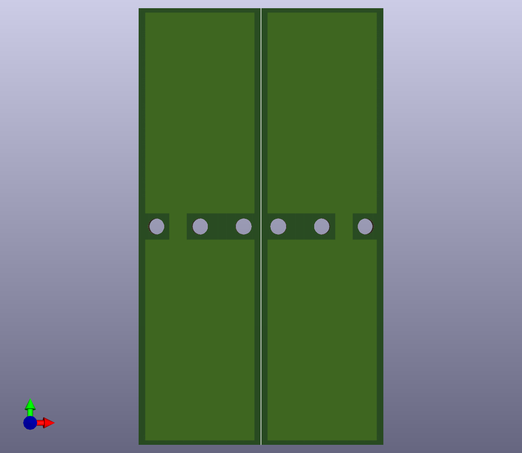
SlidePlate is an open-source printed circuit board by profdc9, from the profdc9/TMatchPCB repository on GitHub. It is a 2-layer board of 56 × 100 mm with 10 parts on 2 nets, routed with 14 tracks and 0 vias.
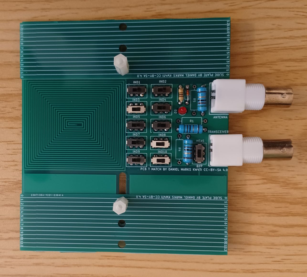
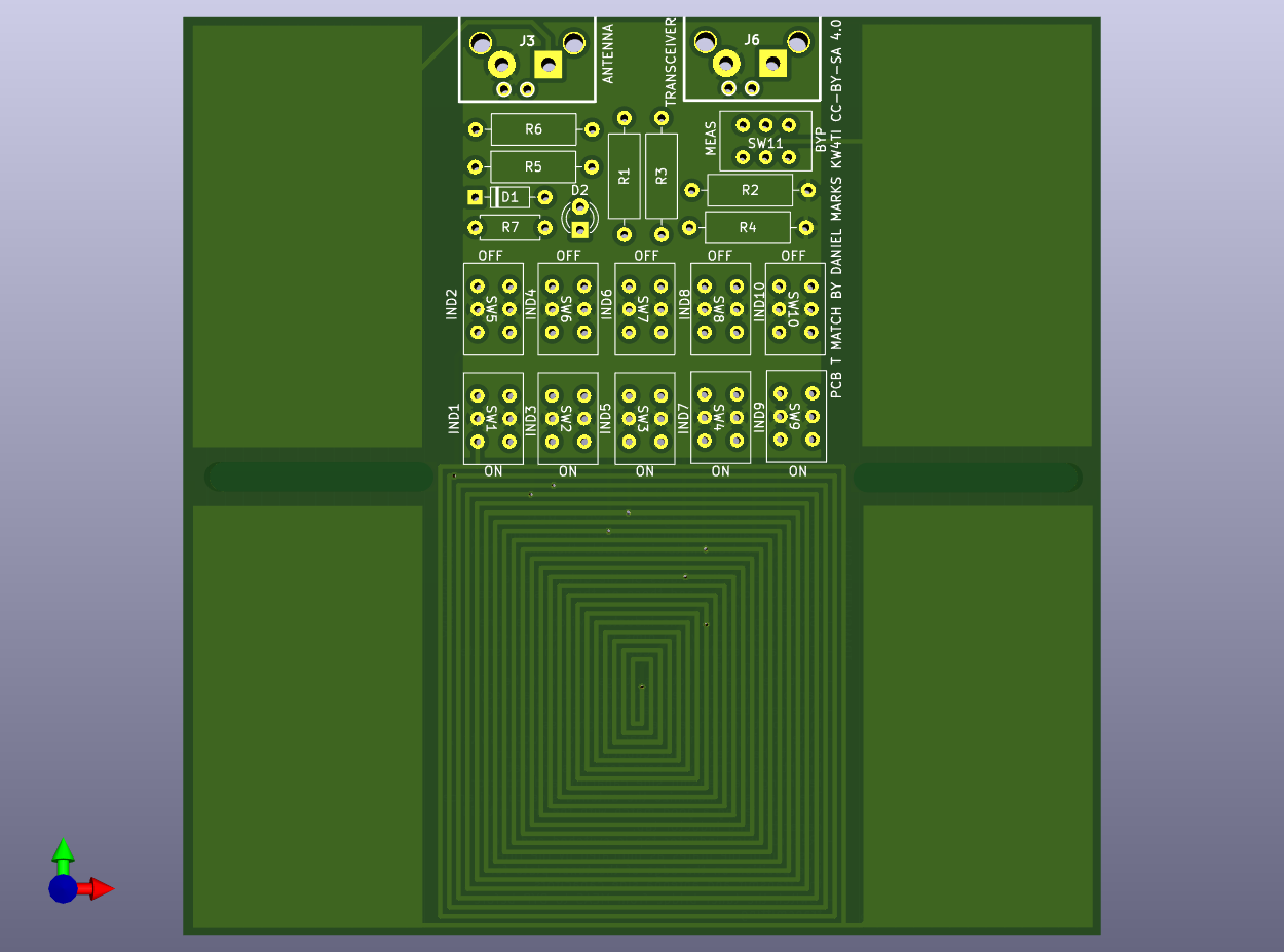
This is a QRP antenna tuner with the capacitor and inductor implemented on a PCB. The capacitor is a split-stator capacitor that is tuned by sliding a second PCB over the tuner PCB to change the contact area. The inductor is a spiral inductor with eight taps with switches for selecting the tap. There is a resistive bridge built into the tuner to aid in tuning the antenna. Ruled lines are drawn on the silkscreen so that the capacitor positions can be noted.
The moving plate is bolted through a hole to and a slot to the antenna tuner plate, with the copper sides (sides without the rulings) face-to-face. Washers should be used on both sides of the plates to spread out the clamping force, with a screw or bolt head on the bottom side, and a wing nut on the top side, to make the two plates easy to loosen, slide, and retighten in a new position.
The rough guide to tuning a T-match.
| Qty | Value | Footprint | References |
|---|---|---|---|
| 6 | MountingHole | MountingHole:MountingHole_3.7mm | H1, H2, H3, H4, H5, H6 |
| 4 | Conn_01x01 | SlidePlate:CapPlate | J1, J2, J3, J4 |
It measures 56 × 100 mm and has 2 copper layers, 1.6 mm thick.
10 parts. The full list of its parts is on this page, with links to each part's symbol and footprint where PCBKit's library has them.
From the profdc9/TMatchPCB repository on GitHub, at the commit this page was made from: the board is SlidePlate/SlidePlate.kicad_pcb and its schematic OneSlidePlate/SlidePlate.kicad_sch. PCBKit opens the board in the browser, with nothing to install.
Its repository states no licence, so its author keeps all rights: ask profdc9 before reusing the design.
profdc9/TMatchPCB
An adjustable T Match where the capacitors and inductors are on the PCB.

gusmanb/logicanalyzer
24 channel, 100Msps logic analyzer hardware and software

byrantech/laptop
anyon_e, a highly integrated, high end, open source laptop. Attempt the impossible.

joeycastillo/Sensor-Watch
A board replacement for the classic Casio F-91W wristwatch


OLIMEX/OLINUXINO
OLINUXINO is Open Source / Open Hardware, low cost from EUR 24 Linux Industrial grade Single Board Computer capable to operate -25+85C

rusefi/rusefi
rusefi - GPL internal combustion engine control unit

VoronDesign/Voron-Hardware
Cool Hardware designed by the Voron Design group

hoglet67/RGBtoHDMI
Bare-metal Raspberry Pi project that provides pixel-perfect sampling of Retro Computer RGB/YUV video and conversion to HDMI