2 layers56 × 100 mm
SlidePlate
profdc9/TMatchPCB
An adjustable T Match where the capacitors and inductors are on the PCB.
10 parts19

 profdc9/TMatchPCB19
An adjustable T Match where the capacitors and inductors are on the PCB.
TMatchPCB is an open-source printed circuit board by profdc9, from the profdc9/TMatchPCB repository on GitHub. It is a 2-layer board of 100 × 100 mm with 28 parts on 10 nets, routed with 200 tracks and 9 vias.
Its parts include 11 switches, 7 resistors, 6 connectors and 2 diodes.
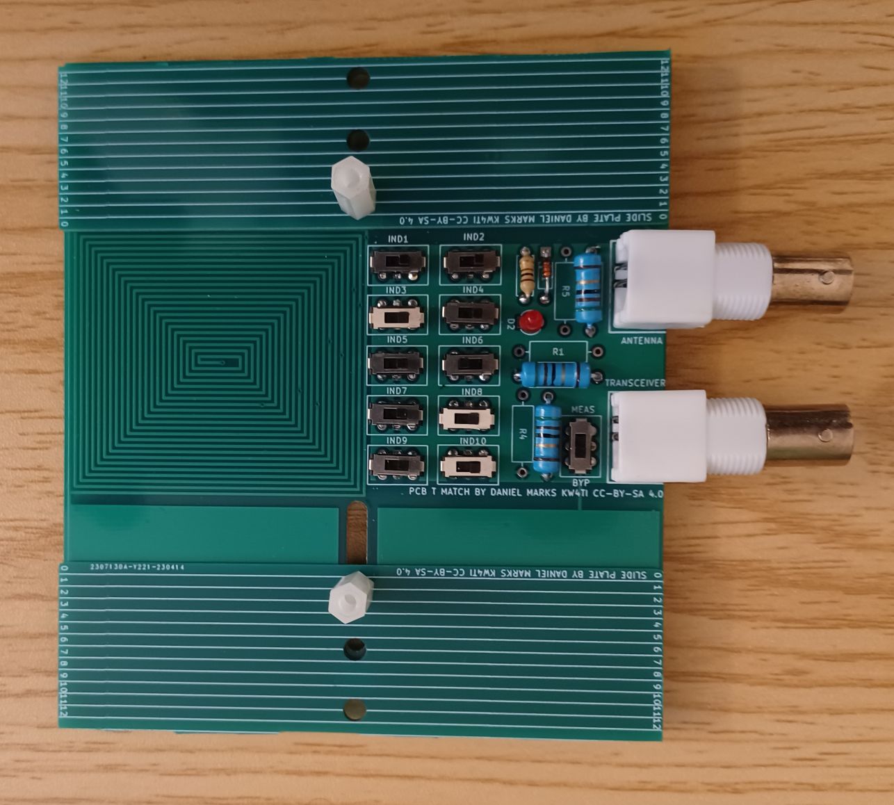
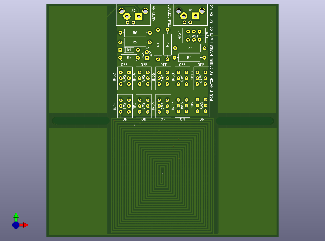
This is a QRP antenna tuner with the capacitor and inductor implemented on a PCB. The capacitor is a split-stator capacitor that is tuned by sliding a second PCB over the tuner PCB to change the contact area. The inductor is a spiral inductor with eight taps with switches for selecting the tap. There is a resistive bridge built into the tuner to aid in tuning the antenna. Ruled lines are drawn on the silkscreen so that the capacitor positions can be noted.
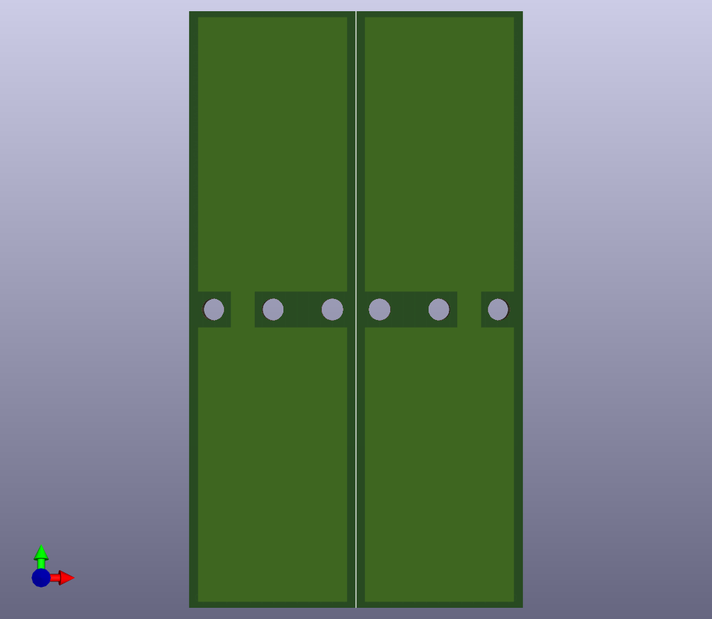
The moving plate is bolted through a hole to and a slot to the antenna tuner plate, with the copper sides (sides without the rulings) face-to-face. Washers should be used on both sides of the plates to spread out the clamping force, with a screw or bolt head on the bottom side, and a wing nut on the top side, to make the two plates easy to loosen, slide, and retighten in a new position.
The rough guide to tuning a T-match.
| Qty | Value | Footprint | References |
|---|---|---|---|
| 10 | SPST23 | TMatchPCB:SS22NB | SW1, SW2, SW3, SW4, SW5, SW6, SW7, SW8, SW9, SW10 |
| 6 | 100R | Resistor_THT:R_Axial_DIN0309_L9.0mm_D3.2mm_P12.70mm_Horizontal | R1, R2, R3, R4, R5, R6 |
| 4 | CapPlate | TMatchPCB:CapPlate | J1, J2, J4, J5 |
| 2 | BNC | TMatchPCB:bnc_90_1-1337543-0_pad_combo | J3, J6 |
| 2 | MountingHole | TMatchPCB:SlideSlot | H1, H2 |
| 1 | 1N4148 | Diode_THT:D_DO-35_SOD27_P7.62mm_Horizontal | D1 |
| 1 | 470R | Resistor_THT:R_Axial_DIN0207_L6.3mm_D2.5mm_P7.62mm_Horizontal | R7 |
| 1 | LED | LED_THT:LED_D3.0mm | D2 |
| 1 | SW_DPDT_x2 | TMatchPCB:SS22 | SW11 |
It measures 100 × 100 mm and has 2 copper layers, 1.6 mm thick.
28 parts. The full list of its parts is on this page, with links to each part's symbol and footprint where PCBKit's library has them.
From the profdc9/TMatchPCB repository on GitHub, at the commit this page was made from: the board is TMatchPCB/TMatchPCB.kicad_pcb and its schematic OneSlidePlate/SlidePlate.kicad_sch. PCBKit opens the board in the browser, with nothing to install.
Its repository states no licence, so its author keeps all rights: ask profdc9 before reusing the design.
profdc9/TMatchPCB
An adjustable T Match where the capacitors and inductors are on the PCB.

joeycastillo/Sensor-Watch
A board replacement for the classic Casio F-91W wristwatch

TalismanDesign/PocketMage_PDA
An E-Ink PDA device using the ESP32 S3.

rusefi/rusefi
rusefi - GPL internal combustion engine control unit

hackclub/OnBoard
💡 Join 1,000 teenagers and make your first PCB with a $100 grant!

asterics/esp32_mouse_keyboard
ESP32 implementation for HID over GATT Keyboard and Mouse (Bluetooth Low Energy). Including serial API for external modules (similar to Adafruit EZKey HID)


Luos-io/luos_engine
Open-source and real-time orchestrator for cyber-physical-systems, to easily design, test and deploy embedded applications and digital twins.

Chrismettal/EleLab_v2
Cheap DIY lab system for hobbyists and the tinkering folk