Skip to the content
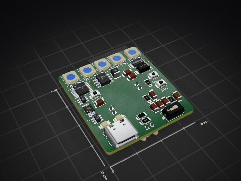
2 layers100 × 100 mmUV Disc Charger, the printed circuit board in 3D

This project presents a UV disc charger designed to illuminate glow-in-the-dark disc golf discs using 100 UV LEDs.

Size
100 × 100 mm
Copper layers
2
Thickness
1.6 mm
Parts
85
Nets
36
Pads
266
Tracks, vias
791, 79
Pours
287
Routed
Yes
KiCad
KiCad 7 (file 20221018)
Created
9 Nov 2024
Updated
19 Feb 2025

Overview

UV Disc Charger is an open-source printed circuit board by potpurri, from the potpurri/UV_Disc_Charger repository on GitHub, published under the Apache-2.0 licence. It is a 2-layer board of 100 × 100 mm with 85 parts on 36 nets, routed with 791 tracks and 79 vias.

It is built around the DW01A, FS8205A and TP4056, with the TPS63020, SI2301 and SMBJ12CA among its other parts. Its parts include 29 diodes, 24 resistors, 11 capacitors, 6 connectors and 4 ICs. It belongs with the power boards of this library.

Main components

8

README

README.md

Overview

This project presents a UV disc charger designed to illuminate glow-in-the-dark disc golf discs using 100 UV LEDs.

The circuit is powered by a LiPo battery, which is charged through a TP4056 with DW01A protection. The LEDs are driven by a TPS63020 buck/boost converter, and the battery is charged via a USB-C port.

Note: This project is a work in progress, aimed at exploring and learning more about these technologies.

Features

The board includes the following components:

  • TP4056: Monitors and manages the charging process.
  • DW01A Protection: Ensures safe charging of the LiPo battery.
  • TPS63020 Buck/Boost Converter: Efficiently drives 100 UV LEDs.
  • USB-C Port: Enables battery charging.
  • Adjustable Charging Current: The charging current is set using resistor R9, with the following settings:
Resistor (Ω)Charging Current (mA)
10k130
4k7280
3k400
2k580
1k5780
1k21000

Image showing the battery being charged at approximately 500mA:
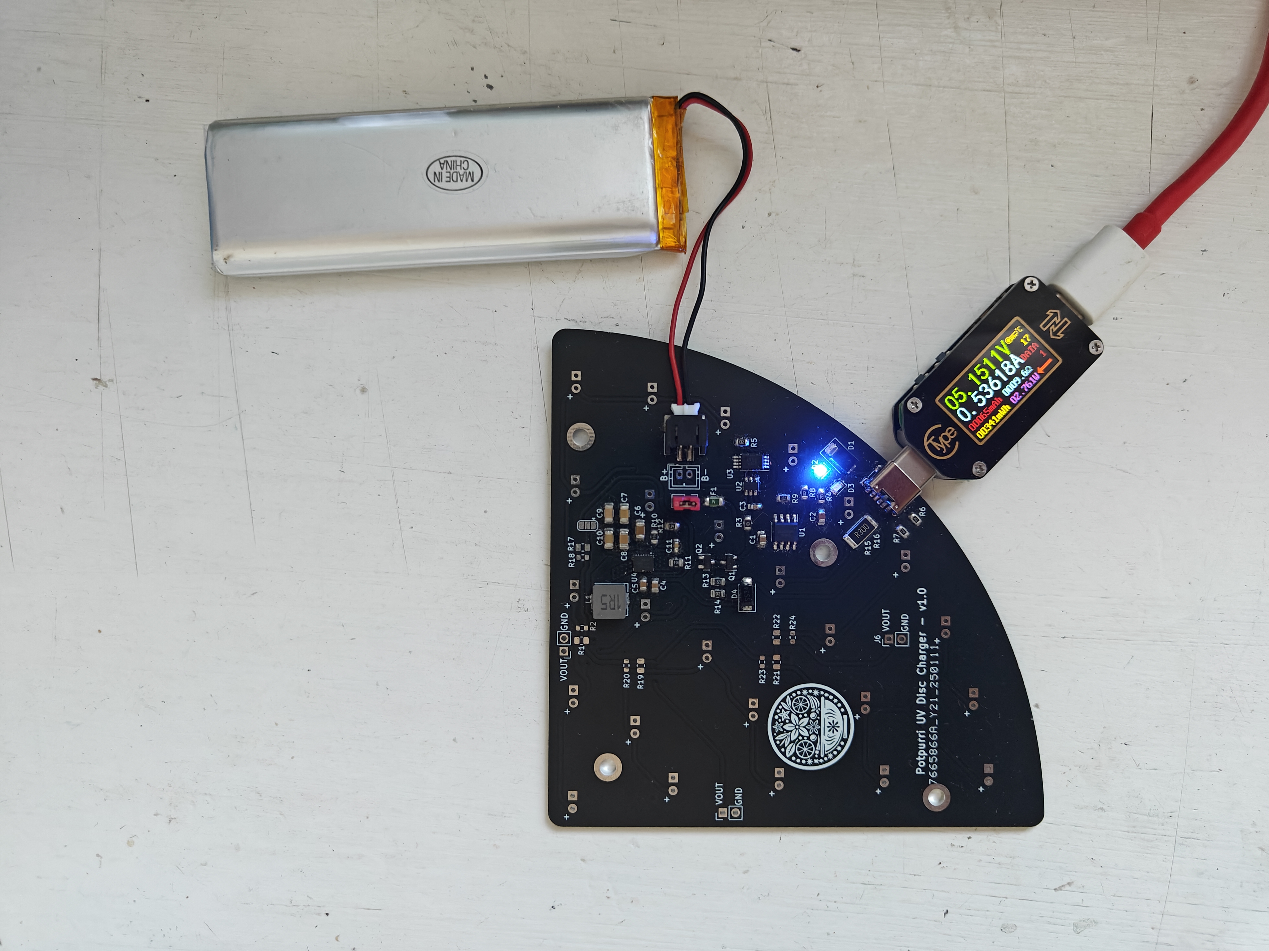
Charging

Images

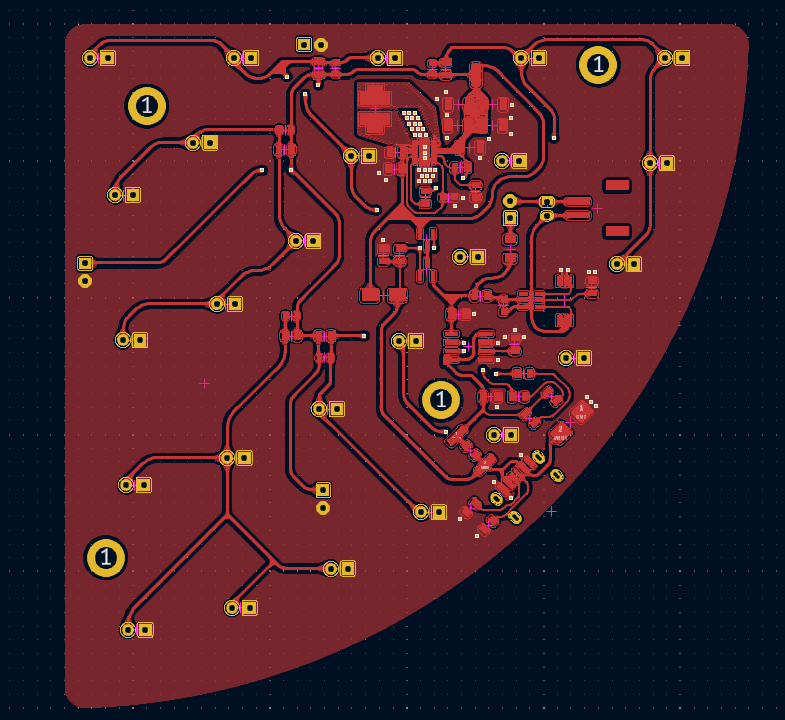
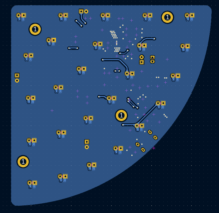
Below are renderings of the PCB:

3D render of the front view of the PCB
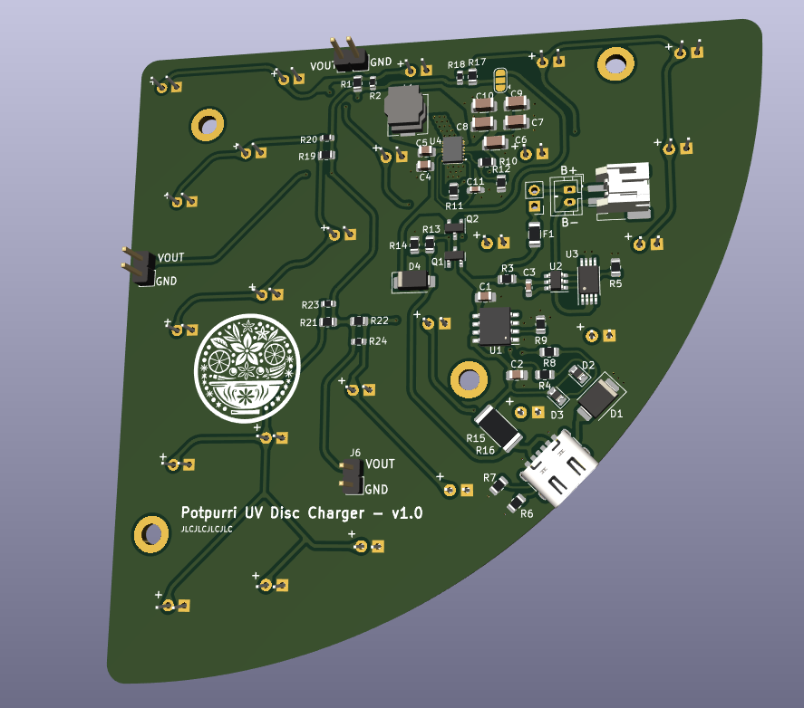
3D Front

3D render of the back view of the PCB
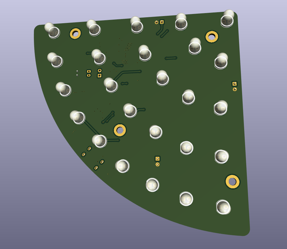
3D Back

Front view of the actual PCB

Front

Back view of the actual PCB

Back

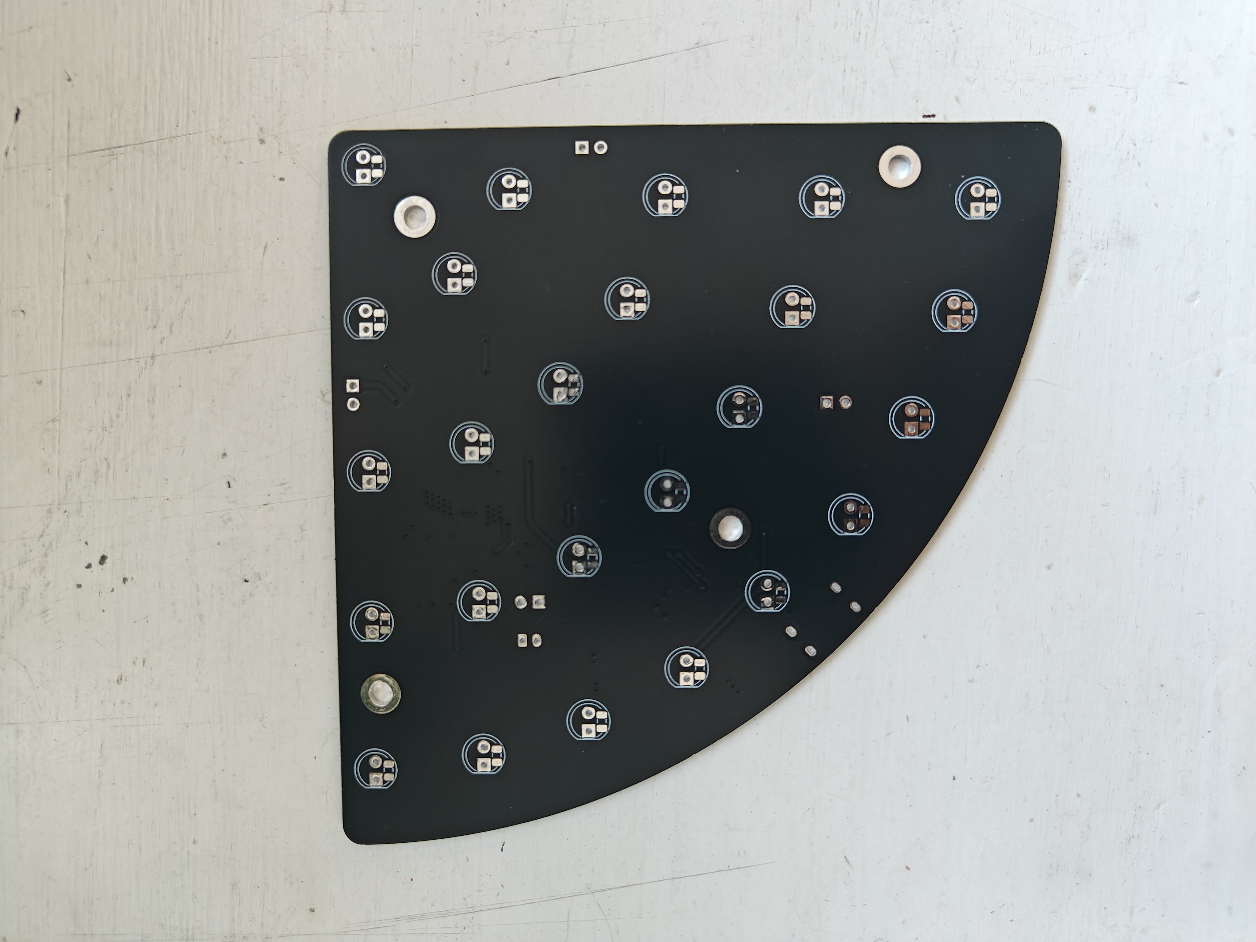
Real PCB Images

Below are images of the actual PCB:

Front view of the real PCB
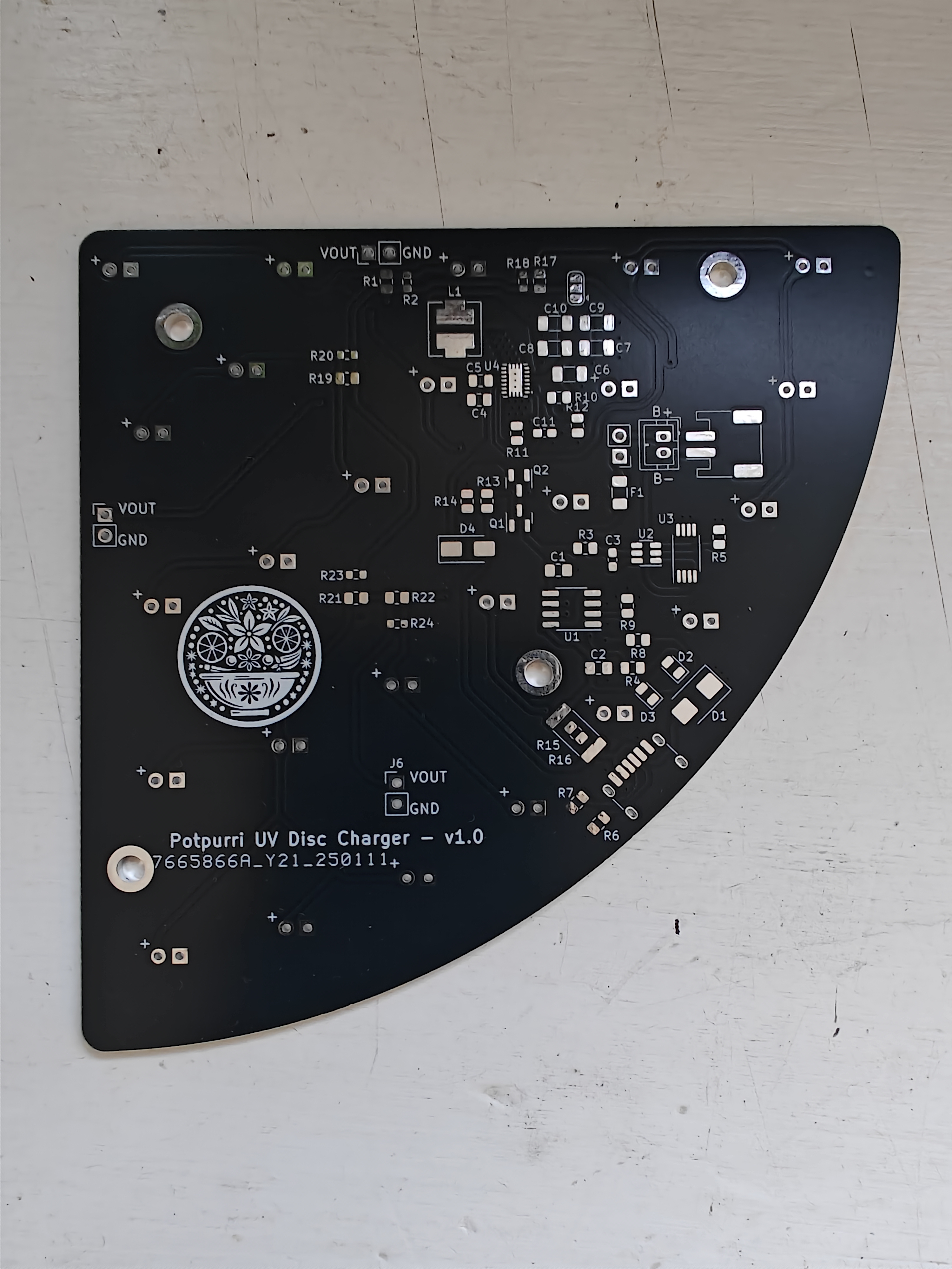
Real PCB Front

Back view of the real PCB

Real PCB Back

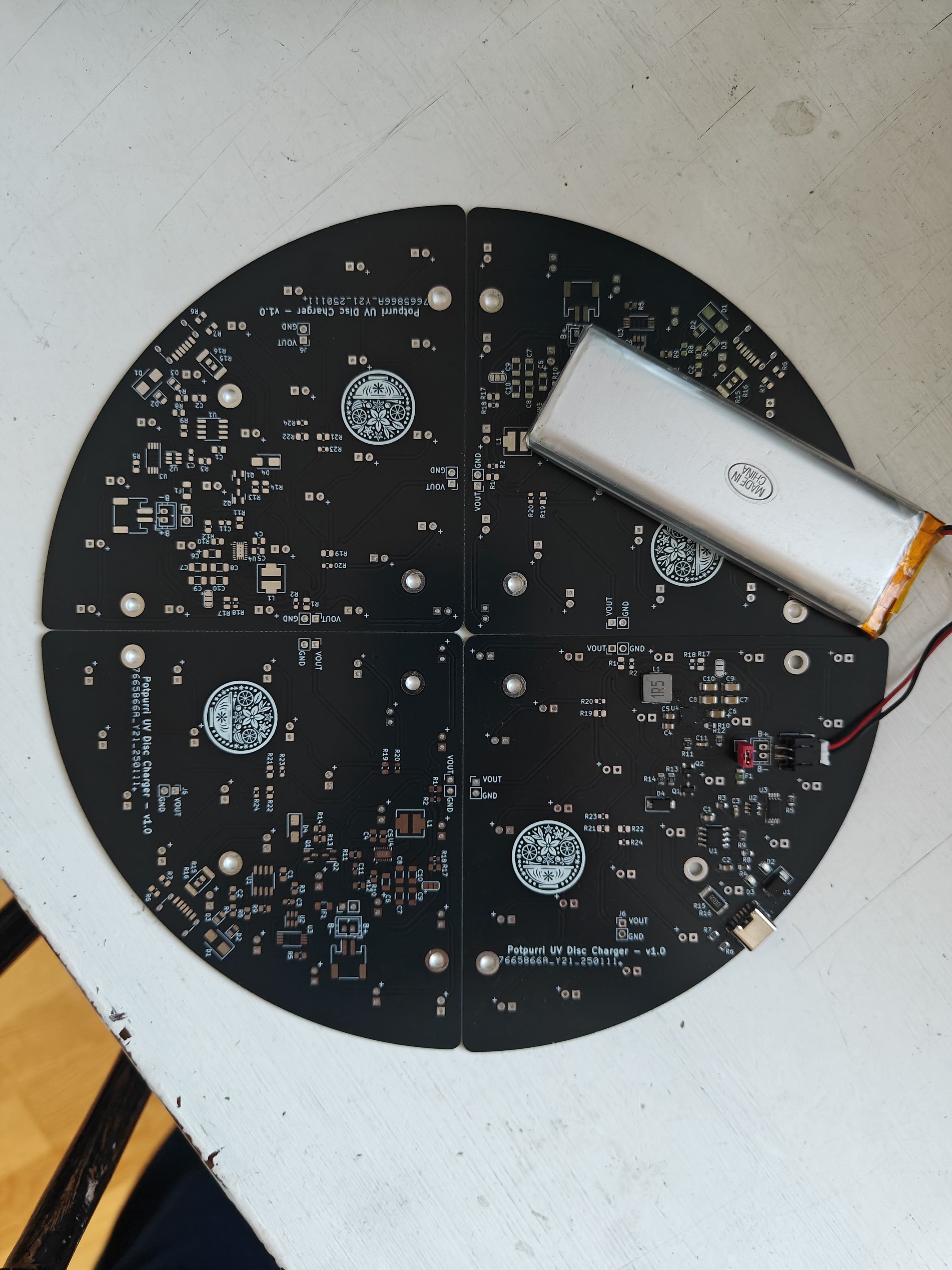
Full Assembly

WORK IN PROGRESS

Full Assembly

Schematics

For detailed schematics, please refer to the schematic PDF.

Parts

85
QtyValueFootprintReferences
25LEDCustom:LED-ThroughHole-And-SMD0805D10, D11, D12, D13, D14, D15, D16, D17, D18, D19, D20, D21, D22, D23, D24, D25 +9
50603Resistor_SMD:R_0603_1608MetricR2, R18, R20, R23, R24
50805Resistor_SMD:R_0805_2012MetricR1, R17, R19, R21, R22
41kResistor_SMD:R_0805_2012MetricR4, R5, R8, R13
422uCapacitor_SMD:C_1206_3216MetricC6, C7, C8, C9
4MountingHoleMountingHole:MountingHole_3.2mm_M3_DIN965_PadH1, H2, H3, H4
3ConnectorConnector_PinHeader_2.54mm:PinHeader_1x02_P2.54mm_VerticalJ3, J5, J6
2100nCapacitor_SMD:C_0603_1608Metric_Pad1.08x0.95mm_HandSolderC3, C11
210uCapacitor_SMD:C_0805_2012MetricC4, C5
210uCapacitor_SMD:C_0805_2012Metric_Pad1.18x1.45mm_HandSolderC1, C2
25k1Resistor_SMD:R_0805_2012MetricR6, R7
2SI2301Package_TO_SOT_SMD:SOT-23Q1, Q2
10R4Resistor_SMD:R_0805_2012MetricR15
11.5AFuse:Fuse_1206_3216MetricF1
1100RResistor_SMD:R_0805_2012MetricR3
1100uCapacitor_SMD:C_1206_3216MetricC10
110kResistor_SMD:R_0805_2012MetricR14
1180kResistor_SMD:R_0805_2012MetricR12
11MResistor_SMD:R_0805_2012MetricR11
11M6Resistor_SMD:R_0805_2012MetricR10
12512 packageResistor_SMD:R_2512_6332MetricR16
12kResistor_SMD:R_0805_2012MetricR9
12u2Custom:Combined CD43 + L 6.3x6.3L1
1DW01APackage_TO_SOT_SMD:SOT-23-6U2
1FS8205APackage_SO:TSSOP-8_4.4x3mm_P0.65mmU3
1GREENDiode_SMD:D_0805_2012MetricD3
1JST PH ConnectorConnector_JST:JST_PH_S2B-PH-SM4-TB_1x02-1MP_P2.00mm_HorizontalJ4
1JST PH ConnectorConnector_JST:JST_PH_B2B-PH-K_1x02_P2.00mm_VerticalJ2
1LOGOLOGOG***
1REDDiode_SMD:D_0805_2012MetricD2
1SMBJ12CADiode_SMD:D_SMBD1
1SS34Diode_SMD:D_SMAD4
1SW_SPSTConnector_PinHeader_2.54mm:PinHeader_1x02_P2.54mm_VerticalSW1
1SolderJumper_3_Bridged12Jumper:SolderJumper-3_P1.3mm_Bridged12_RoundedPad1.0x1.5mmJP1
1TP4056Package_SO:SOP-8_3.76x4.96mm_P1.27mmU1
1TPS63020TPS63020:QFN14-3X4MMU4
1Type-C_6PCustom:USB-C 6 Pin - Long padsJ1

Similar boards

  • 4 layers53 × 33 mmLiPo BuckBoost Charger, the printed circuit board in 3D

    LiPo BuckBoost Charger

    potpurri/LiPo_Charger_TP4056_BuckBoost_TPS63020

    This PCB is designed to safely charge a lithium-ion cell and provide a selectable 3.3V or 5V output. It's equipped with components that ensure safe charging and protection for the battery and supports flexible output…

    63 parts9Apache-2.0
  • 2 layers45 × 30 mmLIR2032-charger, the printed circuit board in 3D

    LIR2032-charger

    potpurri/LIR2032-charger

    Charing board for LIR2032 batteries (or other lithium type button/coin cell batteries with the same diamater and mx voltage of 4.2V)

    36 partsApache-2.0
  • 2 layers35 × 100 mmWalkieTalkie, the printed circuit board in 3D

    WalkieTalkie

    GuzziFlipFlops/ESP32-Walkie-Talkie

    An open source ESPNOW based walkie talkie with a 600 meter tested distance, with an OLED and multiple buttons to interact with

    66 parts7MIT
  • 2 layers30 × 100 mmMoskill, the printed circuit board in 3D

    Moskill

    telagod/moskill

    MosKill - Smart Mosquito Swatter with BLE, Kill Counting & Statistics | ESP32-C3 + KiCad PCB + UniApp

    95 parts2
  • 2 layers35 × 39 mmNex, the printed circuit board in 3D

    Nex

    dialgorithm/nex

    esp32 swarm bots

    60 parts1
  • 2 layers150 × 40 mmBicopter, the printed circuit board in 3D

    Bicopter

    InputBlackBoxOutput/Bicopter

    Design files for a PCB Bicopter

    79 parts1MIT
  • 2 layers116.2 × 95.4 mmMacropad, the printed circuit board in 3D

    Macropad

    sarthakmmishra/macropad

    STM32F103C8T6 based macropad

    99 parts1
  • 2 layers61 × 61 mmVael, the printed circuit board in 3D

    Vael

    dialgorithm/vael

    esp32s3 flight controller

    66 parts

Questions

How big is the UV Disc Charger PCB?

It measures 100 × 100 mm and has 2 copper layers, 1.6 mm thick.

What parts does the UV Disc Charger use?

85 parts, built around the DW01A, FS8205A, TP4056 and TPS63020. The full list of its parts is on this page, with links to each part's symbol and footprint where PCBKit's library has them.

Where can I download the UV Disc Charger KiCad files?

From the potpurri/UV_Disc_Charger repository on GitHub, at the commit this page was made from: the board is UV_Disc_Charger.kicad_pcb and its schematic LEDS.kicad_sch. PCBKit opens the board in the browser, with nothing to install.

Can I use the UV Disc Charger design in my own project?

Its repository publishes it under the Apache-2.0 licence: you may reuse it on that licence's terms (keep the author's notice, and for a copyleft licence share your changes alike).