4 layers83 × 167 mm
Front rear dual can-2026-11-02 before testpoint swap
johnb302/cmu-embedded
Repo for distributed embedded systems at CMU, 18-449
327 parts

 PolybiusBiotech/led_beacon
The PCBA and firmware for the controllable LED Beacons.
Emf beacon is an open-source printed circuit board by PolybiusBiotech, from the PolybiusBiotech/led_beacon repository on GitHub. It is a 2-layer board of 68.4 × 36.7 mm with 134 parts on 113 nets, routed with 694 tracks and 300 vias.
It is built around the CA-IS3092W, ESP32-C3-WROOM-02-H4 and TPS565208DDC, with the TPS82140SILR, AO3400A and B6B-PH-SM4-TB among its other parts. Its parts include 44 resistors, 37 capacitors, 14 connectors, 11 transistors and 6 ICs. It belongs with the ESP32 and RISC-V boards of this library.


Upgrading cheap LED beacons for professional DMX/Art-Net stage control.
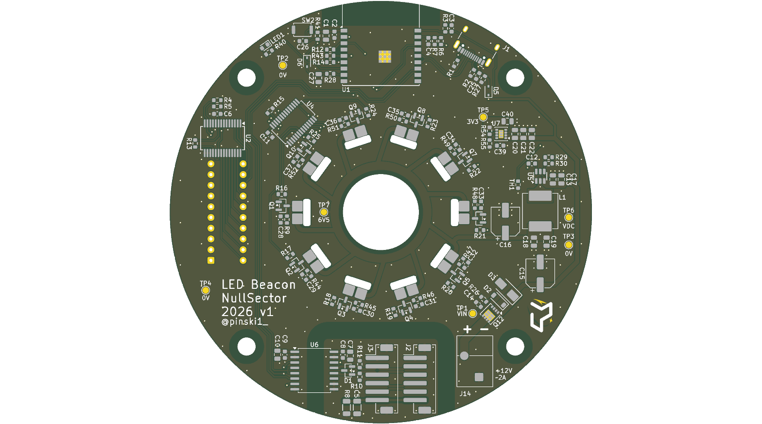
/hardware: KiCAD project files (Version 9.0.7)./firmware: PlatformIO project (Arduino/ESP-IDF framework)./mechanical: 3D-printable housing (.STEP)./docs: Specification, schematics and design calculations./docs on every push./firmware folder in VS Code.0x00 is off0xFF is full brightness0x00 is fully on0x01 strobes at 0.2Hz0xFF strobes at 20HzCommissioned for Null Sector for EMF Camp 2026.
| Qty | Value | Footprint | References |
|---|---|---|---|
| 10 | 100R | Resistor_SMD:R_0603_1608Metric | R16, R17, R18, R19, R20, R21, R22, R23, R24, R25 |
| 10 | 10R | Resistor_SMD:R_0603_1608Metric | R9, R44, R45, R46, R47, R48, R49, R50, R51, R52 |
| 10 | 10k | Resistor_SMD:R_0603_1608Metric | R3, R7, R12, R13, R14, R26, R27, R30, R41, R43 |
| 10 | 10nF | Capacitor_SMD:C_0603_1608Metric | C28, C29, C30, C31, C32, C33, C34, C35, C36, C37 |
| 10 | AO3400A | Package_TO_SOT_SMD:SOT-23 | Q1, Q2, Q3, Q4, Q5, Q6, Q7, Q8, Q9, Q10 |
| 10 | Conn_01x02 | Pinski1_parts:LED_Stick | J4, J5, J6, J7, J8, J9, J10, J11, J12, J13 |
| 9 | 100nF | Capacitor_SMD:C_0603_1608Metric | C2, C4, C6, C8, C9, C11, C12, C25, C26 |
| 9 | 10uF 25V | Capacitor_SMD:C_0805_2012Metric | C1, C7, C10, C13, C17, C20, C21, C22, C27 |
| 7 | TestPoint | TestPoint:TestPoint_Pad_D1.5mm | TP1, TP2, TP3, TP4, TP5, TP6, TP7 |
| 4 | MountingHole | MountingHole:MountingHole_4.3mm_M4 | H1, H2, H3, H4 |
| 3 | 22uF 10V | Capacitor_SMD:C_0805_2012Metric | C18, C19, C40 |
| 2 | 1k0 | Resistor_SMD:R_0603_1608Metric | R4, R5 |
| 2 | 4k7 | Resistor_SMD:R_0603_1608Metric | R10, R11 |
| 2 | 5k1 | Resistor_SMD:R_0603_1608Metric | R1, R2 |
| 2 | 75k | Resistor_SMD:R_0603_1608Metric | R29, R54 |
| 2 | B6B-PH-SM4-TB | Connector_JST:JST_PH_B6B-PH-SM4-TB_1x06-1MP_P2.00mm_Vertical | J2, J3 |
| 1 | 0R0 | Resistor_SMD:R_0603_1608Metric | R15 |
| 1 | 100nF 50V | Capacitor_SMD:C_0603_1608Metric | C14 |
| 1 | 100uF 16V | Capacitor_SMD:CP_Elec_6.3x5.7 | C16 |
| 1 | 100uF 25V | Capacitor_SMD:CP_Elec_6.3x7.7 | C15 |
| 1 | 1M0 | Resistor_SMD:R_1206_3216Metric | R8 |
| 1 | 1nF | Capacitor_SMD:C_0603_1608Metric | C39 |
| 1 | 1nF 2kV | Capacitor_SMD:C_1206_3216Metric | C5 |
| 1 | 1uF 50V | Capacitor_SMD:C_0603_1608Metric | C3 |
| 1 | 24k | Resistor_SMD:R_0603_1608Metric | R55 |
| 1 | 2k7 | Resistor_SMD:R_0603_1608Metric | R40 |
| 1 | 470R | Resistor_SMD:R_0603_1608Metric | R28 |
| 1 | 62k | Resistor_SMD:R_0603_1608Metric | R6 |
| 1 | B16WS | Diode_SMD:D_SOD-323 | D5 |
| 1 | BAT54WS | Diode_SMD:D_SOD-323 | D6 |
| 1 | BZT52C10 | Diode_SMD:D_SOD-123 | D2 |
| 1 | CA-IS3092W | Package_SO:SOIC-16W_7.5x10.3mm_P1.27mm | U6 |
| 1 | Conn_01x02 | emf_beacon_library:MX250-3.5-02P-A-GY01-Cu-A | J14 |
| 1 | DMP3013SFV | Package_SON:Diodes_PowerDI3333-8 | Q12 |
| 1 | ESP32-C3-WROOM-02 | RF_Module:ESP32-C3-WROOM-02 | U1 |
| 1 | KT-0603R | LED_SMD:LED_0603_1608Metric | LED1 |
| 1 | MCP23017T-E/SS | Package_SO:SSOP-28_5.3x10.2mm_P0.65mm | U2 |
| 1 | MWSA0804S-3R3MT | Inductor_SMD:L_Vishay_IHLP-3232 | L1 |
| 1 | NCP18XH103F03RB | Resistor_SMD:R_0603_1608Metric | TH1 |
| 1 | PCA9685PW,118 | Package_SO:TSSOP-28_4.4x9.7mm_P0.65mm | U4 |
| 1 | SM712 | Package_TO_SOT_SMD:SOT-23 | D1 |
| 1 | SMAJ15A | Diode_SMD:D_SMA | D3 |
| 1 | SW_DIP_x10 | Button_Switch_THT:SW_DIP_SPSTx10_Slide_9.78x27.58mm_W7.62mm_P2.54mm | SW1 |
| 1 | TPS565208 | Package_TO_SOT_SMD:SOT-23-6 | U5 |
| 1 | TPS82140SILR | Package_LGA:Texas_SIL0008D_MicroSiP-8-1EP_2.8x3mm_P0.65mm_EP1.1x1.9mm | U7 |
| 1 | TS-1088-AR02016 | Button_Switch_SMD:SW_Push_SPST_NO_Alps_SKRK | SW2 |
| 1 | USB_C_Receptacle_USB2.0_16P | Connector_USB:USB_C_Receptacle_HCTL_HC-TYPE-C-16P-01A | J1 |
The 133 most common of 134 parts.
It measures 68.4 × 36.7 mm and has 2 copper layers, 1.6 mm thick.
134 parts, built around the CA-IS3092W, ESP32-C3-WROOM-02-H4, TPS565208DDC and TPS82140SILR. The full list of its parts is on this page, with links to each part's symbol and footprint where PCBKit's library has them.
From the PolybiusBiotech/led_beacon repository on GitHub, at the commit this page was made from: the board is hardware/emf_beacon.kicad_pcb and its schematic hardware/ctrl.kicad_sch. PCBKit opens the board in the browser, with nothing to install.
Its repository states no licence, so its author keeps all rights: ask PolybiusBiotech before reusing the design.
johnb302/cmu-embedded
Repo for distributed embedded systems at CMU, 18-449

GeoffreyKassis/led_grow_light
USB-C PD grow light in two assemblies: an FR-4 controller (MAINBOARD/) and a one-layer aluminum LED panel (LEDBOARD/), joined by an 8-wire 2×4 IDC harness.

kjeller/orbiter_keyboard
Repo for my symmetrical 52-key split keyboard KiCad project

misko/prompt2device
The separate vNext PCB skill and orchestrator package is available alongside the reference workflow below; existing projects keep their accepted toolchain until an explicit migration.

bornier-dev/bornier
Open source EtherCAT slaves for machine tools running LinuxCNC: hardware, firmware and tooling.


Xerolux/IDM-Smart-Climate-Platform
Diese Platine empfängt Temperatur- und Feuchtewerte aus Home Assistant und simuliert gegenüber der IDM AERO ALM den originalen Temperatur-/Feuchtesensor.

HeyPCB/power-kit
Six open power and charging boards: KiCad 10, JLCPCB-ready, CERN-OHL-S-2.0