2 layers52.8 × 55 mm
ILDAWaveX16
stanleyondrus/ILDAWaveX16
ILDAWaveX16 is an open-source, high-resolution, wireless laser DAC with SD-card playback, network control, and ILDA output.
95 parts42

 Pollex/MFM-Module-RS485
A MultiFlexMeter (MFM) sensor module. The hardware is a generic carrier: RS-485 + 1-Wire, with a software-selectable sensor supply rail (3.6 V / 5 V / 12 V).
Module is an open-source printed circuit board by Pollex, from the Pollex/MFM-Module-RS485 repository on GitHub. It is a 4-layer board of 59.3 × 37.5 mm with 56 parts on 78 nets, routed with 342 tracks and 94 vias.
It is built around the SP3485CN-L, TLV61048DBV and TPS22810DBV, with the RBE01VYM6AFHTR and PTS810SJG250SMTRLFS among its other parts. Its parts include 23 resistors, 11 capacitors, 7 diodes, 6 ICs and 3 connectors. It belongs with the STM32 boards of this library.


A MultiFlexMeter (MFM) sensor module. The hardware is a generic carrier: RS-485 + 1-Wire, with a software-selectable sensor supply rail (3.6 V / 5 V / 12 V). The firmware (RIOT-OS, STM32L010) is likewise mostly generic — it powers the rail, talks to the host over I2C, and runs a measurement FSM. The current application reads a LinkBlue dissolved-oxygen (DO) sensor over Modbus RTU.
The module is a slave to the MFM host: the host powers it, triggers a measurement over I2C, then reads back the result.
| Feature | Notes |
|---|---|
| Sensor bus | RS-485 (Modbus RTU) and 1-Wire |
| Sensor supply | Boost rail, selectable 3.6 V / 5 V / 12 V (FB divider) |
| Host link | I2C slave (MFM register protocol) |
| MCU | STM32L010 (mfm-module board) |
The rail voltage is a compile-time choice (boost_voltage in main.c),
currently 12 V for the DO sensor. KiCad sources live in hardware/; fab
outputs are generated separately and shipped as release assets.
Prerequisites: the arm-none-eabi GCC toolchain, plus the RIOT submodule and
an out-of-tree I2C-slave patch.
git submodule update --init --recursive
git apply --directory=RIOT 0001-i2c-slave.patch   # I2C slave mode, not yet upstream
make                                               # build
make flash                                         # build + flash via SWD
FW_VERSION is stamped from git describe --tags, so build from a tagged
commit for a meaningful version string.
Pass as make VAR=1. Defaults are production values.
| Flag | Default | Effect |
|---|---|---|
FAT | 0 | 1 = factory-acceptance loop: power rails, init Modbus + DO, read forever. Bench bring-up only. |
LOW_POWER | 1 | 0 = block all PM modes so the CPU busy-waits in idle, keeping the SWD link and breakpoints reliable for debugging. |
DEBUG_LED | 0 | 1 = blink LED1 with the FSM state and LED2 with the last error code. |
The host drives the module through the MFM I2C register protocol — firmware version, init, measurement start/status/data, and error. Register map and semantics: see the MultiFlexMeter host protocol spec.
A measurement cycle: host writes MEAS_START → firmware powers the rail,
validates VSensor, brings up Modbus, reads the DO sensor, publishes the payload
→ host reads MEAS_DATA. On a measurement failure the firmware returns to
IDLE and exposes an app error code (also blinked on LED2) in the error
register for the host to read. An invalid FSM state instead halts in ERROR;
the host recovers by power-cycling.
stateDiagram-v2
    [*] --> SYSTEM_INIT: power on
    SYSTEM_INIT --> IDLE: GPIO, I2C, ADC up
    IDLE --> MFR_INIT: host: manufacturer init
    MFR_INIT --> IDLE
    IDLE --> MEASURING: host: measure
    MEASURING --> IDLE: done or failure
    ERROR --> ERROR: halt on invalid state (host power-cycles)

    state MEASURING {
        [*] --> SENSORS_INIT
        SENSORS_INIT --> DO_CONF: rail OK, sensor probed
        DO_CONF --> DO_READ: no-op (no DO config)
        DO_READ --> MEASURE_FINISH
        MEASURE_FINISH --> [*]
    }
FAT=1 replaces this flow with a standalone read loop (APP_STATE_FAT) that
doesn't wait for an I2C command.
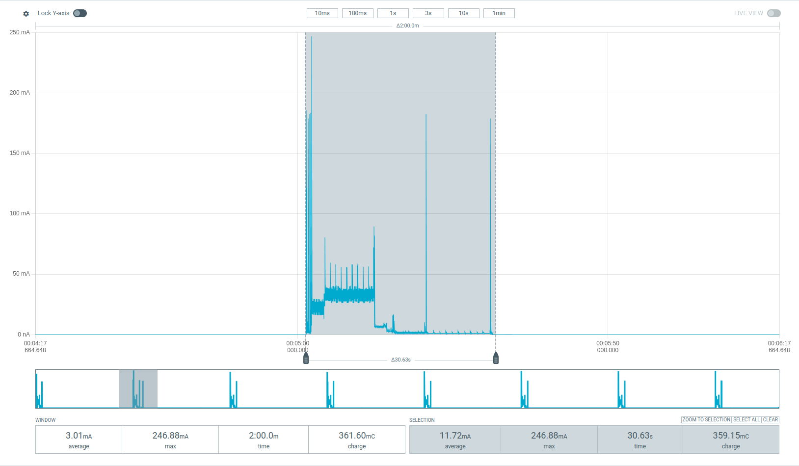
Measured at the MultiFlexMeter main board's supply, so the figures include the main board's own consumption, not just this module. Captured on a dev build (less power-efficient than production) with LoRa at SF7.
A measurement cycle's active phase lasts about 30 s and draws roughly 360 mC (11.7 mA average, 247 mA peak).
MEAS_DATA returns an 8-byte, packed, little-endian struct. Fields are copied
verbatim from the sensor's Modbus input registers — the firmware does no scaling
or validation, so each value is a raw fixed-point integer the consumer must
scale (and range-check) itself.
| Offset | Field | Type | Range | Scale | Unit |
|---|---|---|---|---|---|
| 0 | DO value | uint16 | 0–2000 | ×0.01 | mg/L |
| 2 | DO saturation | uint16 | 0–200 | ×0.1 | % |
| 4 | Electrode signal | uint16 | 0–1000 | raw | — |
| 6 | Temperature | int16 | -100–1300 | ×0.1 | °C |
Apply the scale to recover the physical value — e.g. a DO field of 742 is
7.42 mg/L.
| Qty | Value | Footprint | References |
|---|---|---|---|
| 7 | 100n | Capacitor_SMD:C_0603_1608Metric | C1, C2, C3, C4, C5, C6, C16 |
| 7 | 10k | Resistor_SMD:R_0603_1608Metric | R4, R6, R7, R8, R9, R10, R25 |
| 5 | 0E | Resistor_SMD:R_0603_1608Metric | R1, R11, R12, R16, R26 |
| 3 | 4k7 | Resistor_SMD:R_0603_1608Metric | R22, R24, R28 |
| 2 | 10n | Capacitor_SMD:C_0603_1608Metric | C7, C8 |
| 2 | 10u | Capacitor_SMD:C_0805_2012Metric | C9, C11 |
| 2 | 180E | Resistor_SMD:R_0603_1608Metric | R2, R3 |
| 2 | LED_Small | LED_SMD:LED_0603_1608Metric | D1, D2 |
| 2 | TPS22810DBV | Package_TO_SOT_SMD:SOT-23-6 | U4, U6 |
| 2 | TVS Vr=5V | Diode_SMD:D_SOD-323F | D5, D6 |
| 1 | 10u | Inductor_SMD:L_Sunlord_SWPA5040S | L1 |
| 1 | 120 | Resistor_SMD:R_0603_1608Metric | R23 |
| 1 | 13k3 | Resistor_SMD:R_0603_1608Metric | R15 |
| 1 | 140k | Resistor_SMD:R_0603_1608Metric | R14 |
| 1 | 30k | Resistor_SMD:R_0603_1608Metric | R5 |
| 1 | 40k2 | Resistor_SMD:R_0603_1608Metric | R18 |
| 1 | 80k6 | Resistor_SMD:R_0603_1608Metric | R13 |
| 1 | Conn_01x04 | Connector_Phoenix_MC:PhoenixContact_MC_1,5_4-G-3.81_1x04_P3.81mm_Horizontal | J3 |
| 1 | D_Small_Filled | SOD323-HE:SOD323-HE | D7 |
| 1 | FerriteBead_Small | Inductor_SMD:L_0603_1608Metric | FB1 |
| 1 | LOGO | footprints:logo-pollex-15mm | G*** |
| 1 | Onewire | Connector_Phoenix_MC:PhoenixContact_MC_1,5_3-G-3.81_1x03_P3.81mm_Horizontal | J4 |
| 1 | PCIEx4 | Connector_PCBEdge:BUS_PCIexpress_x4 | U1 |
| 1 | PTS810SJG250SMTRLFS | Button_Switch_SMD:SW_SPST_PTS810 | SW1 |
| 1 | SM712_SOT23 | Package_TO_SOT_SMD:SOT-23 | D4 |
| 1 | SP3485CN | Package_SO:SOIC-8_3.9x4.9mm_P1.27mm | U5 |
| 1 | STM32L010C6Tx | Package_QFP:LQFP-48_7x7mm_P0.5mm | U2 |
| 1 | SWD Connector | Connector_PinHeader_1.27mm:PinHeader_2x05_P1.27mm_Vertical_SMD | J1 |
| 1 | TLV61048 | Package_TO_SOT_SMD:SOT-23-6 | U3 |
| 1 | TVS Vr=14V | Diode_SMD:D_SMF | D3 |
| 1 | ~ | Package_TO_SOT_SMD:SOT-363_SC-70-6 | Q1 |
The 55 most common of 56 parts.
It measures 59.3 × 37.5 mm and has 4 copper layers, 1.58 mm thick.
56 parts, built around the SP3485CN-L, TLV61048DBV, TPS22810DBV and RBE01VYM6AFHTR. The full list of its parts is on this page, with links to each part's symbol and footprint where PCBKit's library has them.
From the Pollex/MFM-Module-RS485 repository on GitHub, at the commit this page was made from: the board is hardware/module.kicad_pcb and its schematic hardware/BuckBooster.kicad_sch. PCBKit opens the board in the browser, with nothing to install.
Its repository states no licence, so its author keeps all rights: ask Pollex before reusing the design.
stanleyondrus/ILDAWaveX16
ILDAWaveX16 is an open-source, high-resolution, wireless laser DAC with SD-card playback, network control, and ILDA output.


FabianSchwartau/OBSPro
Version of the OpenBikeSensor hardware optimized for PCBA


mpiraux/OpenTRV-ESP
An open-source and open-hardware thermostatic radiator valve based on the ESP32C6 and the 28BYJ-48 stepper motor.

marcusmueller/12V_step_up
General purpose Step-Up converter

