Skip to the content
2 layers121 × 90 mmPower distrib 100A to 5+1 outputs, the printed circuit board in 3D

Power distrib 100A to 5+1 outputs

pollen-robotics/elec_relay_R2

Relay 24V/100A + fuses to power Reachy 2

Size
121 × 90 mm
Copper layers
2
Thickness
1.71 mm
Parts
42
Nets
17
Pads
95
Tracks, vias
48, 64
Pours
19
Routed
Yes
KiCad
KiCad 9.0 (file 20241229)
Created
19 Aug 2025
Updated
27 Apr 2026

Overview

Power distrib 100A to 5+1 outputs is an open-source printed circuit board by pollen-robotics, from the pollen-robotics/elec_relay_R2 repository on GitHub, published under the Apache-2.0 licence. It is a 2-layer board of 121 × 90 mm with 42 parts on 17 nets, routed with 48 tracks and 64 vias.

It is built around the TSR 1-2450E. Its parts include 12 connectors, 12 fuses, 3 diodes, 2 switches and 1 IC. It belongs with the home automation and IoT boards of this library.

Main components

1

README

README.md

"Relay" for R2

"Relay for R2" is dedicated to sourcing every parts of R2 (except the mobile base).
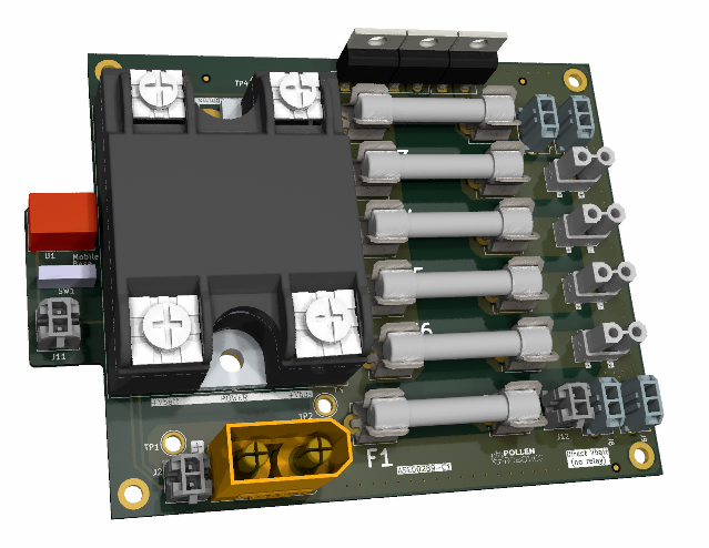
3d_view

High inrush current

We have been facing issues with the power supply of R2. It concerns battery/BMS/relais. Took some sweat to fix that and still a bit of time to be 100% confident about the fix. Long story short, the sum of the capacitor of R2 are putting pressure on the supply equipment. An extra capacitor has been added over the relay, this soften the startup of R2.

Here are the debugging steps and explanations:
  • the mobile base relay has turned obsolete and has been swapped by the manufacturer equivalent
  • BMS was triggered from time to time of some batteries
  • new reference of the relay has been tested and we discovered that is started faster (1ms on the older ref. and 10us on the newer)
  • at the same moment, torso relay were regularly burning. As no burning prints were observed and no fuse melted, we thought at overvoltage.
  • tries with an extra heavy-duty diode: the loop is then closed with the help of the freewheeling diodes of the motor side. No effect has been seen, the zener diodes on the BLDC controller are probably doing a good job.
  • measurements of the battery current shows 500A+ inrush current. Those are pretty impressive and slightly over specs of the relay (500A for 1ms, 100A continuous). Starting a single BLDC driver is still quite few Amps, it induces a voltage decrease on the battery (even though BMS is given for 135A for 10s)
  • total amont of capacitor of R2's torso is 7500uF
  • U=RI, we give a try with thiner cable (sic!) and then a big resistor (0,44 Ohms - 100W) directly on the battery. Thermal dissipation is pretty big (~85°C) an charging is a disaster (~30% of the capacity is lost and 100% charge is just impossible).
  • Finally a trick is found: adding a big capacitor on the terminals of the relay: this will charge when the robot is off, then discharge/supply the BLDC drivers when the relay is turned on.
  • measurements show that this operate well: the capacitor is more reactive than the relay and it taking care of a good part of the inrush current.
  • a large amont of tries is done, switching on/off while moving, charging. A simulution is made to verify the operation of the trick

measurement

  • light blue: relay_in (that is to say: battery voltage), it is almost shorted 100us after startup, one can then see the charge of the capacitor of R2
  • yellow: relay_out.
  • blue: current (10mV/A), directly on the battery output, first bump is made by the torso relay, second is the mobile base. This screenshot is made with the extra capacitor. Thought it looks like a big amont of current, it is below 500A so it will be handle by the torso relay
  • white: reference current (10mV/A), before the adding of the capacitor.

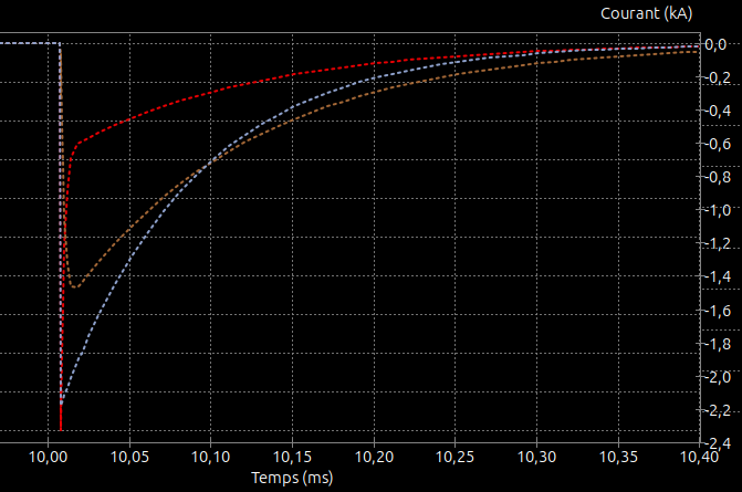
measurement

  • blue: inrush current of the original wiring
  • brown: inrush current after adding the extra capacitor over relay
  • red: extra capacitor current

Basically

  • Designed with KiCAD 7, updated in 9

Parts

42
QtyValueFootprintReferences
12Fuse HolderLibrary_Pollen:Schurter_ 8040.0001F7, F8, F9, F10, F11, F12, F13, F14, F15, F16, F17, F18
4MicroFit 2Library_Pollen:Molex_Micro-Fit_436500221J3, J8, J9, J10
4MountingHole_PadMountingHole:MountingHole_3.2mm_M3_ISO14580_Pad_TopBottomH1, H2, H3, H6
4XT30Library_Pollen:Amass_XT30UPB-FJ4, J5, J6, J7
3DNP FiducialFiducial:Fiducial_1mm_Mask2mmFID1, FID2, FID3
3Diode - 30A free wheelPackage_TO_SOT_THT:TO-220-2_VerticalD1, D2, D3
3MicroFit 2Library_Pollen:Molex_Micro-Fit_3.0_43045-0212_2x01_P3.00mm_VerticalJ2, J11, J12
2Wire_to_PCBTestPoint:TestPoint_Plated_Hole_D3.0mmTP1, TP2
2Wire_to_PCBTestPoint:TestPoint_THTPad_D4.0mm_Drill2.0mmTP3, TP4
1DNP Logo Pollen 2021Library_Pollen:Logo_Pollen_2021_sqH5
1SW_SPDT_312Library_Pollen:EOZ_09.03201.02SW1
1Sensata_D06D100Library_Pollen:Sensata_D06D100K1
1TSR1-2450ELibrary_Pollen:Converter_DCDC_TRACO_TSR1-xxxxE_THTU1
1XT90Library_Pollen:Amass_XT90PB-MJ1

Similar boards

  • 4 layers65 × 70 mmSwr meter, the printed circuit board in 3D

    Swr meter

    F6ITU/vswr_meter

    PD0LEW reflectometer fork

    70 parts3
  • 4 layers80 × 80 mmPICO iot, the printed circuit board in 3D

    PICO iot

    Ayan-nova/Design-of-a-Raspberry-PICO-Iot-Device-on-4-Layer-PCB-Design-With-Sensor-And-More

    Design a Raspberry Pi Pico W-based Industrial IoT Gateway and Edge Controller using Kicad software.

    60 parts1
  • 2 layers57 × 49.7 mmGp2026, the printed circuit board in 3D

    Gp2026

    baloghr/usonic

    KiCad 9 project gp2026 (hardware revision 1.01): schematic, PCB, custom footprints (Library.pretty) and 3D models (packages3D).

    17 parts1
  • 2 layers110.6 × 83.1 mmMain board proto, the printed circuit board in 3D

    Main board proto

    ismailEngineer/omniwheel-robot

    a small protoype to educate the control system of 3 OmniWheel Robot

    35 parts1
  • 2 layers101 × 70 mmHECU, the printed circuit board in 3D

    HECU

    twitch0001/HECU

    v1 - UWEFS HybridCU (Teensy 4.1 Based)

    40 parts1
  • 4 layers99 × 146 mmCarte principale, the printed circuit board in 3D

    Carte principale

    Unimakers/CDR-2027

    Ce repo est un site de documentation réalisé par l'équipe des première et deusième années pré-ingénieur de l'école Unilasalle-Amiens, membre de l'association de robotique Unimaker, dans le cadre de leur participation à…

    156 parts1
  • 2 layers24.2 × 24.1 mmVPC, the printed circuit board in 3D

    VPC

    Archfx/evie

    Camaro6 tweaks

    27 parts
  • 2 layers89 × 72.5 mmAug, the printed circuit board in 3D

    Aug

    augustjf/aug_electrical

    39 parts

Questions

How big is the Power distrib 100A to 5+1 outputs PCB?

It measures 121 × 90 mm and has 2 copper layers, 1.71 mm thick.

What parts does the Power distrib 100A to 5+1 outputs use?

42 parts, built around the TSR 1-2450E. The full list of its parts is on this page, with links to each part's symbol and footprint where PCBKit's library has them.

Where can I download the Power distrib 100A to 5+1 outputs KiCad files?

From the pollen-robotics/elec_relay_R2 repository on GitHub, at the commit this page was made from: the board is power_distrib_100A_to_5+1_outputs.kicad_pcb and its schematic power_distrib_100A_to_5+1_outputs.kicad_sch. PCBKit opens the board in the browser, with nothing to install.

Can I use the Power distrib 100A to 5+1 outputs design in my own project?

Its repository publishes it under the Apache-2.0 licence: you may reuse it on that licence's terms (keep the author's notice, and for a copyleft licence share your changes alike).