4 layers115 × 65 mm
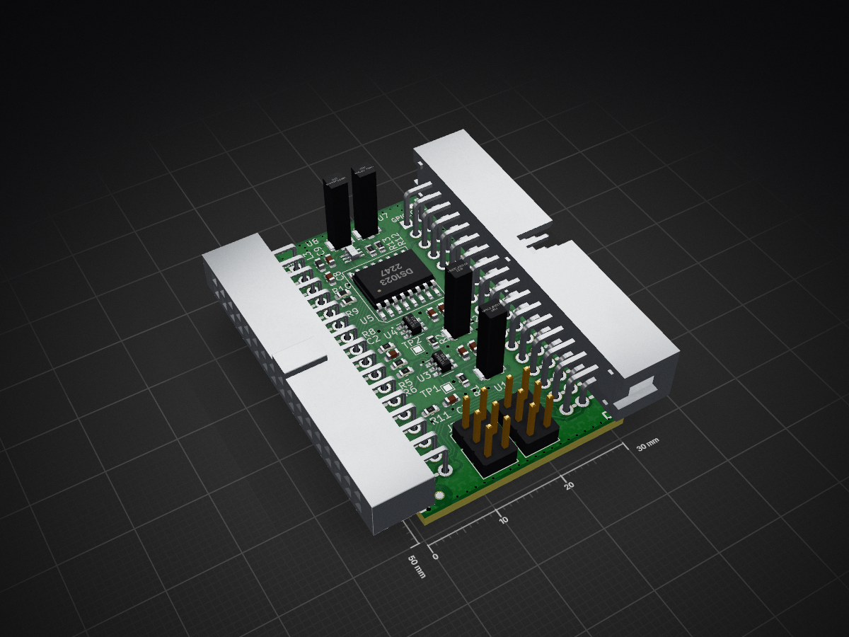
 plex1/ice40_driver_pcb
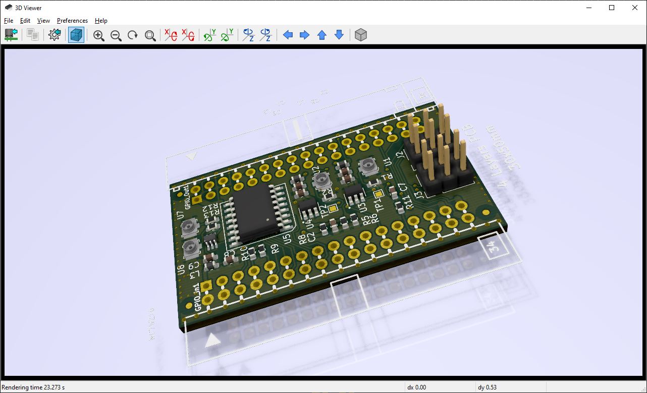
Contains - variable delay IC and - signal drivers and receivers for 50 Ohms UMCC cables.
Signal driver pcb is an open-source printed circuit board by plex1, from the plex1/ice40_driver_pcb repository on GitHub, published under the Apache-2.0 licence. It is a 4-layer board of 30 × 50 mm with 43 parts on 46 nets, routed with 872 tracks and 108 vias.
It is built around the NC7WZ16P6, TLV3501AID and DS1023S-25+. Its parts include 11 resistors, 8 capacitors, 8 ICs, 3 connectors and 3 inductors.


Extension module for iCE40HX1K-EVB or iCE40HX8K-EVB.
Contains
License information should be found in LICENSE.txt
| Qty | Value | Footprint | References |
|---|---|---|---|
| 6 | OLIMEX_Other-FP:Fiducial1x3 | , , , , , | |
| 4 | 2.2k | Resistor_SMD:R_0603_1608Metric | R5, R6, R8, R11 |
| 4 | 2.2uF | Capacitor_SMD:C_0603_1608Metric | C2, C5, C6, C8 |
| 4 | UMCC_50Ohm | IODA_Lib:Molex_734120114_UMC_RF_CONN_Vertical | U1, U2, U7, U8 |
| 3 | 0R | Resistor_SMD:R_0603_1608Metric | R3, R9, R10 |
| 3 | 100nF | Capacitor_SMD:C_0603_1608Metric | C3, C4, C9 |
| 3 | bead | Inductor_SMD:L_0603_1608Metric | L1, L2, L3 |
| 2 | 22R | Resistor_SMD:R_0603_1608Metric | R12, R13 |
| 2 | 50R | Resistor_SMD:R_0603_1608Metric | R1, R2 |
| 2 | Conn_02x03_Odd_Even | Connector_PinHeader_2.54mm:PinHeader_2x03_P2.54mm_Vertical | J2, J3 |
| 2 | TLV3501 | IODA_Lib:SOT-23-6 | U3, U4 |
| 2 | TestPoint | TestPoint:TestPoint_Pad_1.0x1.0mm | TP1, TP2 |
| 1 | 100pF | Capacitor_SMD:C_0603_1608Metric | C7 |
| 1 | BH34R | OLIMEX_Connectors-FP:BH34R | GPIO_Out1 |
| 1 | Conn_01x04 | Connector_Molex:Molex_PicoBlade_53261-0471_1x04-1MP_P1.25mm_Horizontal | J1 |
| 1 | DS1023 | IODA_Lib:SOIC-16_300mil | U5 |
| 1 | IDC34R | OLIMEX_Connectors-FP:IDC34R_PCB | GPIO_In1 |
| 1 | NC7WZ16 | IODA_Lib:SOT65P210X110-6N | U6 |
It measures 30 × 50 mm and has 4 copper layers, 1.6 mm thick.
43 parts, built around the NC7WZ16P6, TLV3501AID and DS1023S-25+. The full list of its parts is on this page, with links to each part's symbol and footprint where PCBKit's library has them.
From the plex1/ice40_driver_pcb repository on GitHub, at the commit this page was made from: the board is signal_driver_pcb.kicad_pcb. PCBKit opens the board in the browser, with nothing to install.
Its repository publishes it under the Apache-2.0 licence: you may reuse it on that licence's terms (keep the author's notice, and for a copyleft licence share your changes alike).


CRImier/MyKiCad
My KiCad boards. Can't be bothered uploading individually anymore, so here you go.

libresmartphone/libresmartphone
This page contains the software used in the open hardware smartphone (libresmartphone)


iic-jku/gf180mcu-jku-projects
This wafer.space tapeout includes various projects from the IICQC at JKU and a TinyWhisper RISC-V from JMU.

LUMERIIX/FrequencyCounter
FPGA based frequnecy counter hard- and software repository
