4 layers68 × 60 mm
RoboCore V2
Plastal-Bot-Builders/RoboCoreDocumentation
RoboCore is a classroom robot kit and coding platform, designed and built in Zambia by Plastal-Bot Builders (Lusaka).
146 partsMIT

 Plastal-Bot-Builders/RoboCoreDocumentation
RoboCore is a classroom robot kit and coding platform, designed and built in Zambia by Plastal-Bot Builders (Lusaka).
RoboCore LineSensor is an open-source printed circuit board by Plastal-Bot-Builders, from the Plastal-Bot-Builders/RoboCoreDocumentation repository on GitHub, published under the MIT licence. It is a 2-layer board of 60 × 24 mm with 25 parts on 16 nets, routed with 187 tracks and 51 vias.
It is built around the TCRT5000 and LM339. Its parts include 11 resistors, 4 capacitors, 4 ICs, 3 diodes and 1 connector.


RoboCore is a classroom robot kit and coding platform, designed and built in Zambia by Plastal-Bot Builders (Lusaka). It has four parts:
This repository holds the design sources for all of it: the PCBs, the mechanical design, the software design and the brand. Pitch decks, grant applications and community posts live elsewhere.
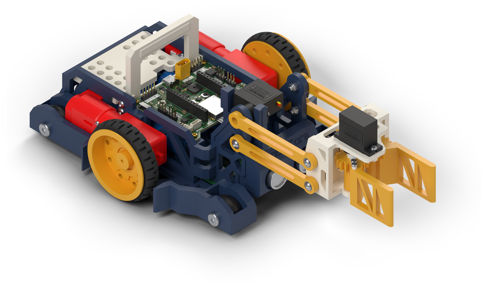 | 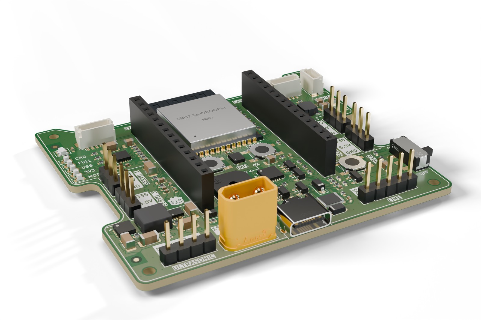 |
| The robot (V2, Fusion 360) | The controller board (V2, KiCad 9) |
An XRP-style robot controller on a 68 × 60 mm, 4-layer board. Everything a classroom robot needs is on one board, and it charges and programs over one USB-C cable.
| Brain | ESP32-S3-WROOM-1-N8R2: dual core, Wi-Fi and Bluetooth LE, 8 MB flash, 2 MB PSRAM. Programs over native USB, so no separate programmer is needed |
| Motors | 2 DC motors with encoders (DRV8411A dual H-bridge, limited to 1.0 A per motor). JST SH 6-pin, matching the SparkFun XRP motors |
| Servos | 4 servo ports on a 5.5 V supply (TPS61089 boost, about 2.5–3 A continuous) |
| Sensors | Ultrasonic port (4-pin), 3-channel line-sensor port (5-pin, analog), Qwiic I2C, and an LSM6DSOX 6-axis motion sensor on board |
| Power | One Li-ion cell, or several in parallel (3.0–4.2 V), on an XT30 plug. Protected against a reversed or over-voltage pack. USB-C charging at 1 A (MCP73871) and a steady 3.3 V from a buck-boost converter |
| On board | RGB LED, buzzer, RESET, BOOT and USER buttons, charge and power LEDs, two 14-pin expansion headers |
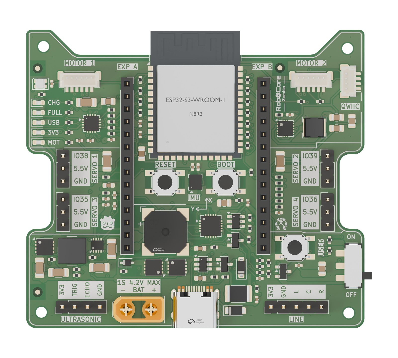 | 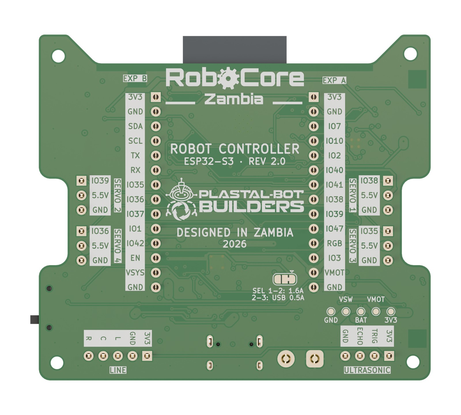 |
| Top: every port labelled on the silkscreen | Underside: pin names and the "Designed in Zambia" artwork |
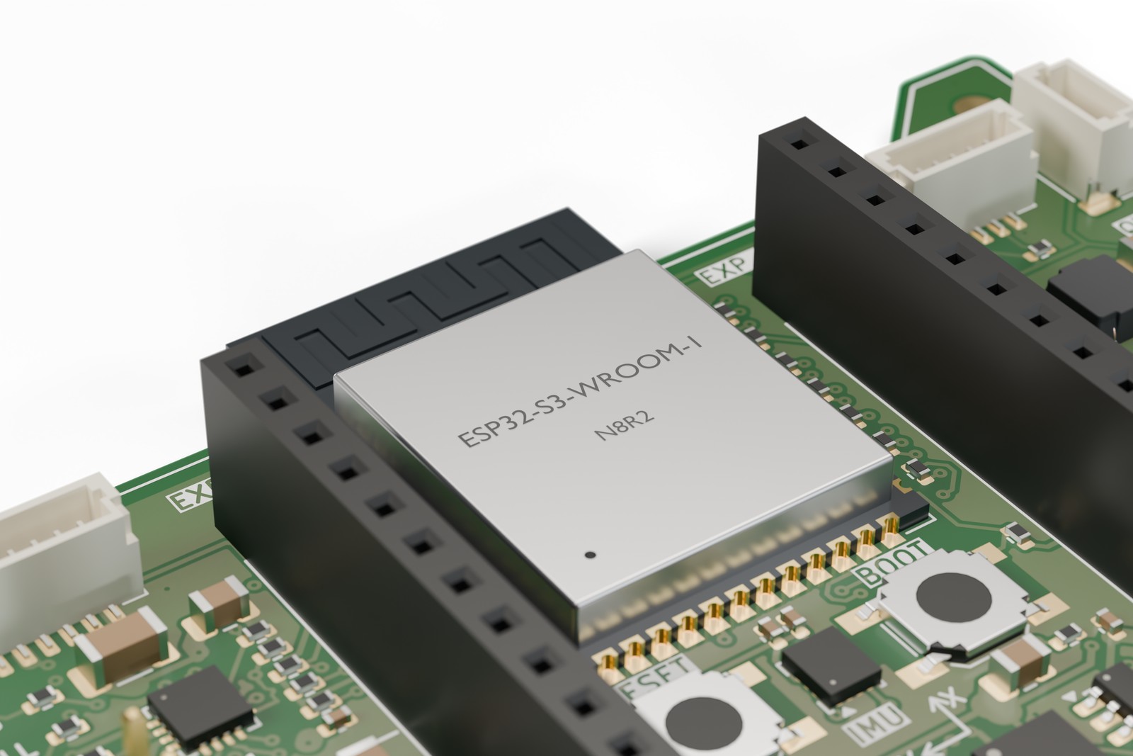 | 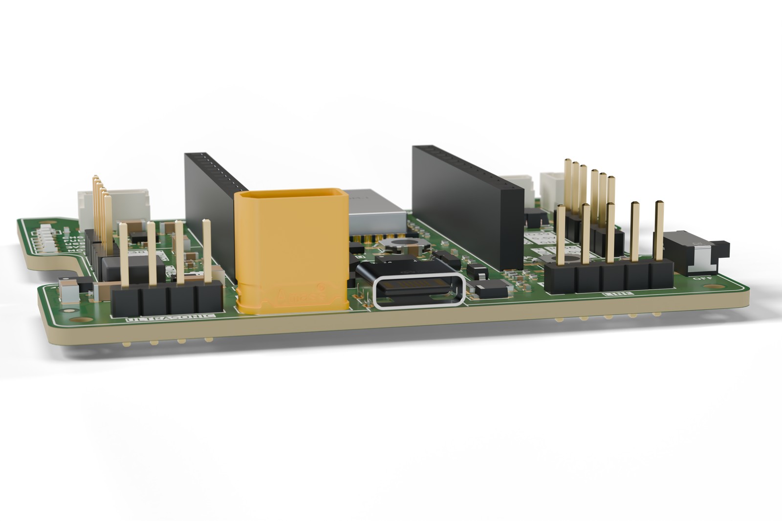 |
| The ESP32-S3 module, buttons and IMU | The connector edge: ultrasonic, battery, USB-C, line sensor, power switch |
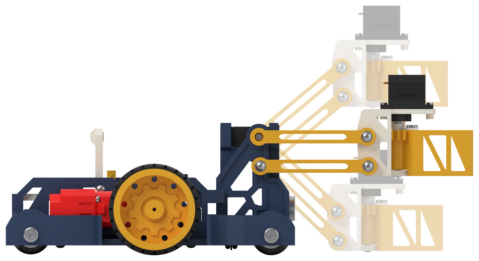
hardware/controller_v2/. Open RoboCore_V2.kicad_pro in KiCad 9.hardware/controller_v2/renders/, full size and 1600 px, with transparent and white backgrounds. Each shot has a map of where every part sits in the image, for pinouts and highlights in the IDE or on the website. See its README.hardware/sensors/. For now the robot uses bought-in modules.The current robot (V3, the V-wheel version): an open printed frame with Warren-truss sides, two encoder motors with 56 mm wheels, four V-wheels in wheel wells, a parallel four-bar lift on one MG90S servo (the gripper stays level from the floor to +40 degrees) and a geared gripper on a second servo. The RoboCore V2 controller sits between the side frames, three 18650 cells lie in a printed cradle, the sonar sits in a housing at the front, and a cream rear deck carries an 8 mm Technic/M4 hole grid. 154 x 286 x 111 mm with the lift level, about 620 g; every part prints flat without supports. The V3 model lives in Fusion 360 (document "RoboCore V3 Robot"); the files below are the earlier V2 robot, kept for reference.
mechanical/robot_v2/RoboCore_V2_Robot.f3d (Fusion 360) and .step (any CAD program).mechanical/robot_v2/fusion/). Its README explains the parameters, the fasteners and the checks: clashes, overhangs, antenna clearance and caster load.mechanical/robot_v2/print/, already in print orientation. Every part prints without supports on a 180 mm bed.mechanical/robot_v2/cardboard/.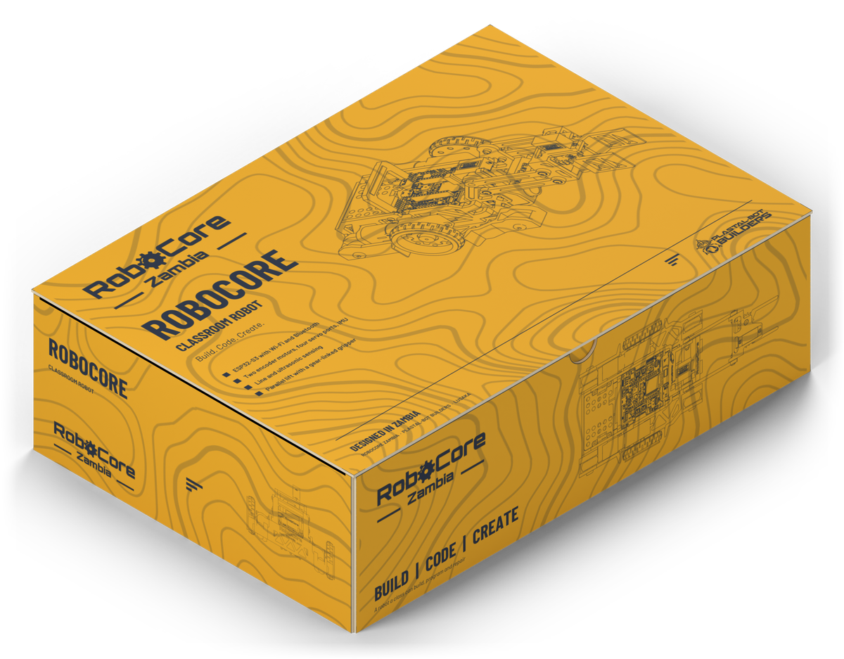 | 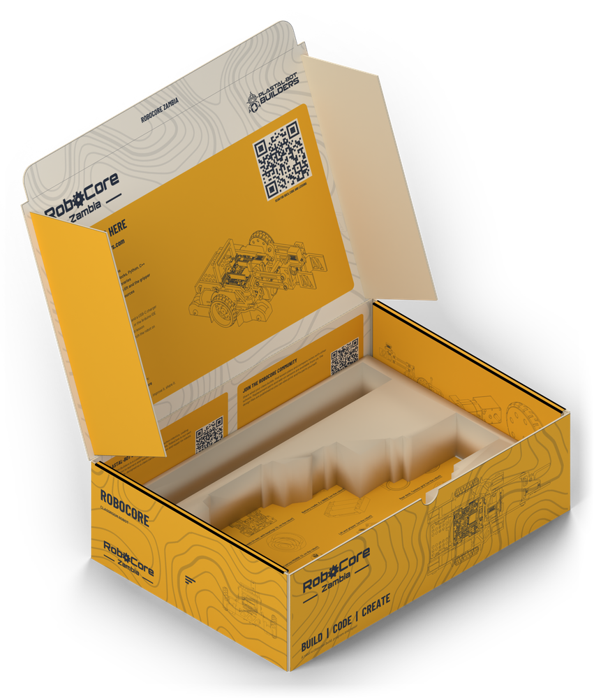 |
A printed mailer box, XRP-style, with the quick-start guide printed inside the lid and an insert with a pocket traced from the robot (lift lowered, jaws on the floor) plus a strip for the cable, screws and card. Outer 303 x 213 x 91 mm. The print-ready 1:1 PDFs are in mechanical/robot_v2/packaging/out_v3/ (generator make_box_v3.py; the V2 box is in out/).
software/ide_design/): the screens of the RoboCore IDE, built in Figma by a plugin. It covers block coding (Google Blockly) and C++ (Monaco), a hardware-first block catalogue, and a behaviour spec. The app itself is developed in its own repository, robocore-ide.software/architecture/): UML and C4 diagrams of the whole platform, also generated into Figma.software/firmware/motion/): an arm-aware braking limiter in C, with tests.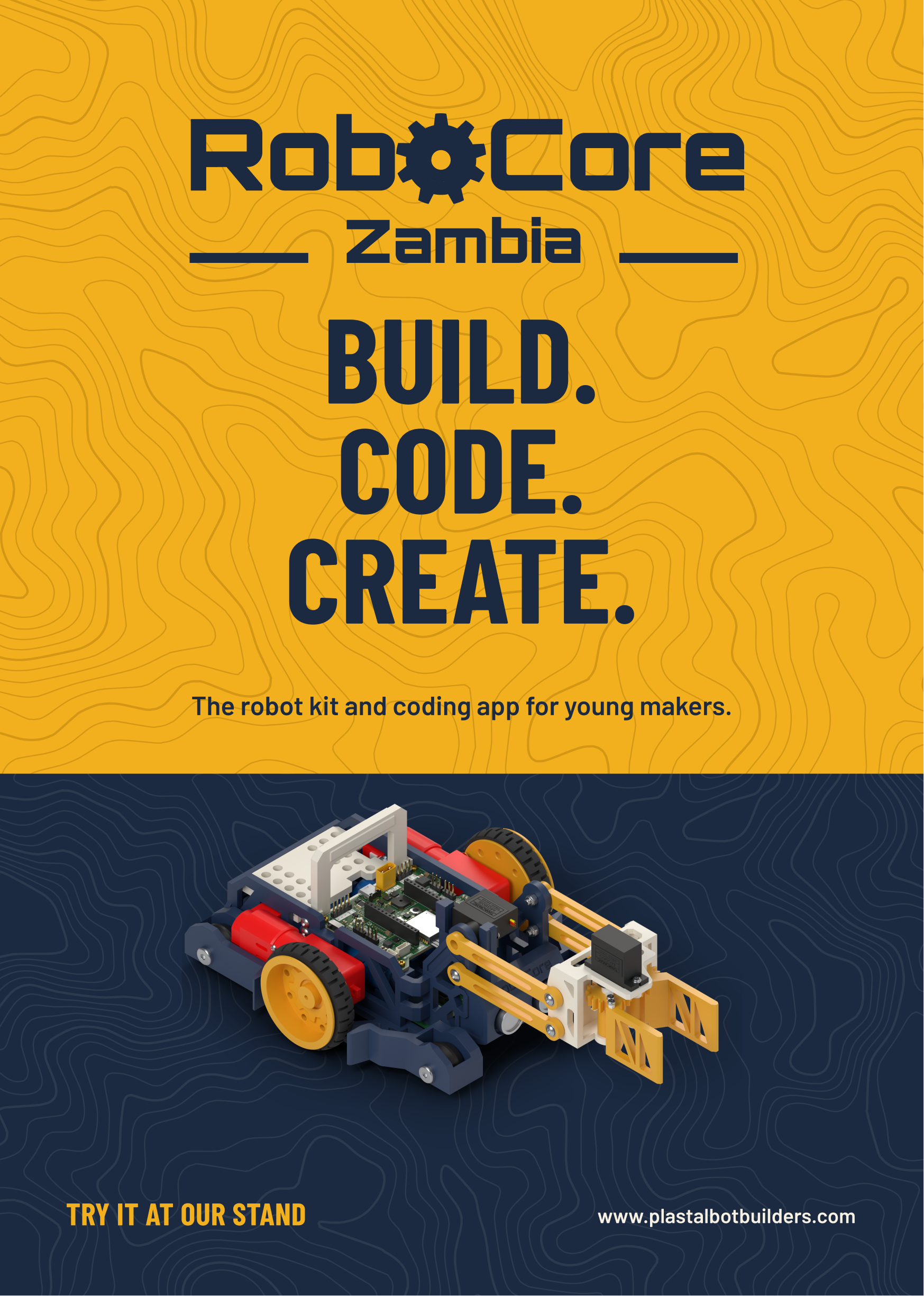 | 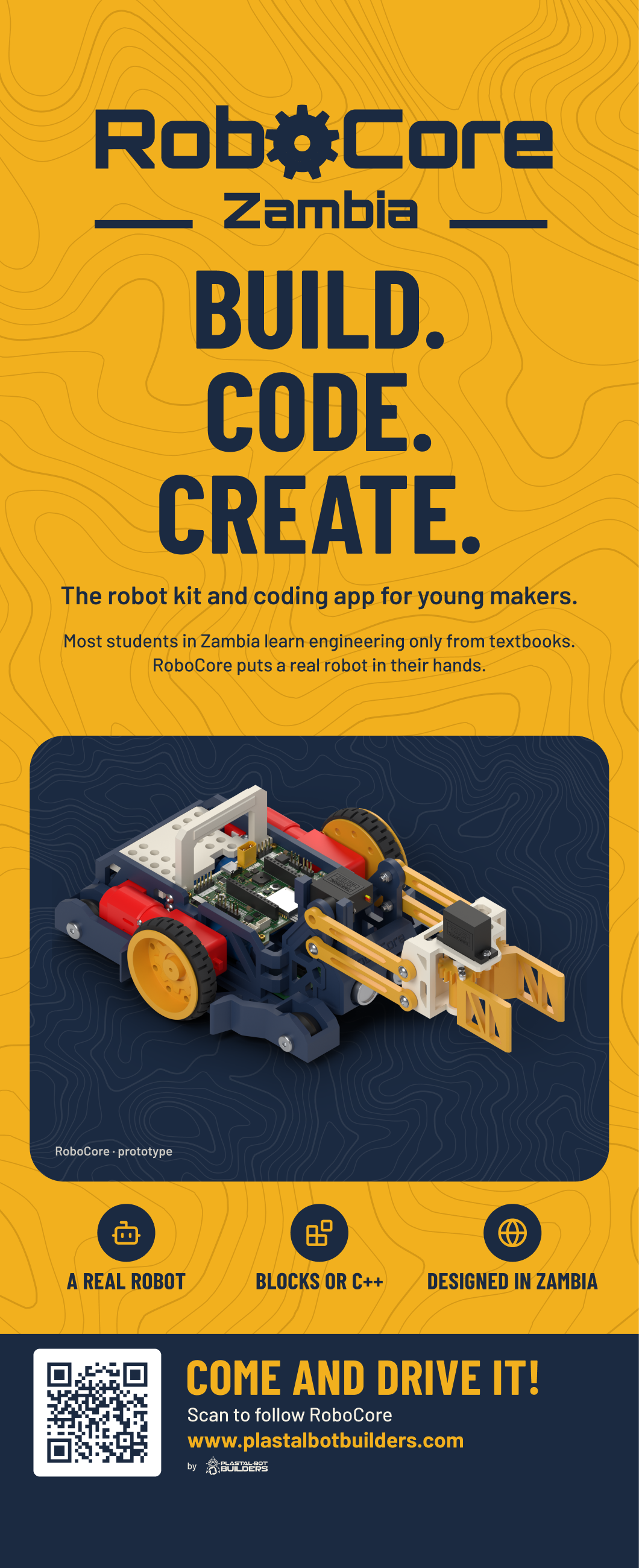 | 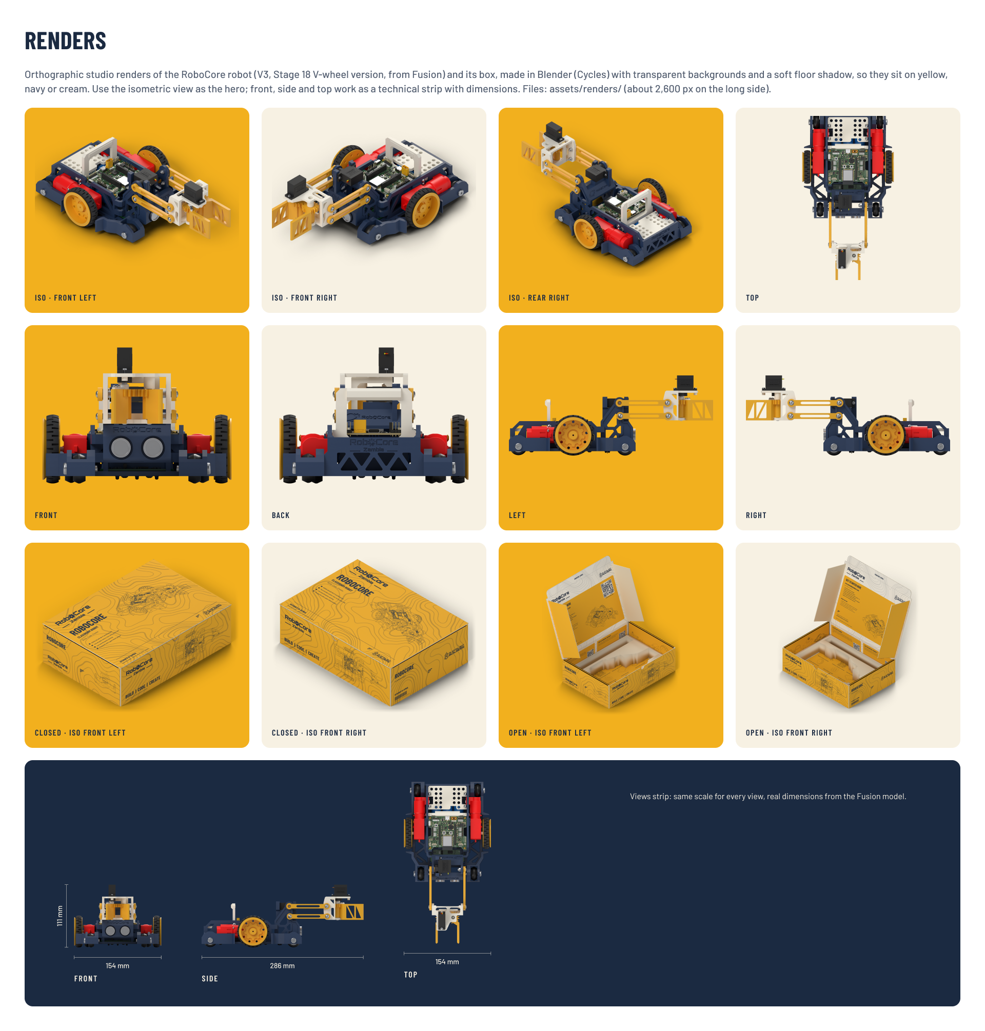 |
Event branding is in design/event_branding/: roll-up, pop-up, banner, A5 flyer, A4 tri-fold and the brand kit, built in Figma by a plugin. The topographic backgrounds are drawn from Copperbelt elevation data.
hardware/          PCB design (KiCad 9)
  controller_v2/     RoboCore V2 controller: project files, libraries (lib/), PCBWay and JLCPCB order
                     packages (fab/), generator, check, costing and Blender render scripts (tools/),
                     silkscreen artwork sources (technicalreference/), studio renders (renders/)
  sensors/           Line sensor (3-channel) and ultrasonic carrier boards for V2
  controller_v1/     RoboCore V1 (ESP32-C3) controller with its fab package and review scripts
  libraries/         Shared symbol and footprint libraries used by V1
  datasheets/        Component datasheets
mechanical/        Mechanical design
  robot_v2/          The Fusion 360 robot: model, Python generator (fusion/), print files (print/),
                     component STEP exports (export/), mailer box (packaging/), cardboard version
                     (cardboard/), vendor models (vendor/), renders
  board_step/        STEP models of the boards, for mechanical integration
  reference/         Motor and XRP reference pictures and models
  chassis_v1_spec/   Specification and script of the V1 chassis
software/          Software
  ide_design/        RoboCore IDE screens (Figma plugin), app icon, block catalogue, behaviour spec
  architecture/      UML + C4 system architecture (Figma plugin)
  firmware/motion/   Arm-aware braking limiter (C, with tests)
design/            Brand
  event_branding/    Roll-up, banner, flyer, tri-fold and brand kit (Figma plugin), topographic maps
docs/              Specification, costing and sourcing, component lists and supplier quote requests,
                   wrong-plug check and errata, schematic PDFs, part photos, A4 technical-reference
                   posters, progress renders, hand-off notes, PCBWay sponsorship request
tools/ sync_from_sources.sh: copies the working sources into this repohardware/controller_v2/RoboCore_V2.kicad_pro in KiCad 9. Project libraries resolve through ${KIPRJMOD}/lib; the V1 project's symbol table points at ../libraries.mechanical/robot_v2/RoboCore_V2_Robot.f3d opens in Fusion 360; the STEP beside it opens anywhere.mechanical/robot_v2/packaging/README.md. The print files are 1:1 PDFs.hardware/controller_v2/tools/blender/render_board.sh re-renders them in Blender 5.1, from the KiCad model.software/ide_design/, software/architecture/ and design/event_branding/ explain how to load and run each plugin.docs/.The design work happens in working folders outside this repo. Copy it in, then commit:
tools/sync_from_sources.sh           # list what changed
tools/sync_from_sources.sh --apply   # copy it in
The script lists every source folder it copies. On a slow connection, push large changes in several small commits.
MIT, see LICENSE. Vendor models under mechanical/robot_v2/vendor/ keep their own licences, noted in each folder's SOURCE.txt.
| Qty | Value | Footprint | References |
|---|---|---|---|
| 3 | 0.1uF | Capacitor_SMD:C_0603_1608Metric | C2, C3, C4 |
| 3 | 10k | Resistor_SMD:R_0603_1608Metric | R2, R4, R6 |
| 3 | 150 | Resistor_SMD:R_0603_1608Metric | R1, R3, R5 |
| 3 | 680 | Resistor_SMD:R_0603_1608Metric | R9, R10, R11 |
| 3 | GREEN | LED_SMD:LED_0603_1608Metric | D1, D2, D3 |
| 3 | TCRT5000 | OptoDevice:Vishay_TCRT5000 | U1, U2, U3 |
| 2 | 100k | Resistor_SMD:R_0603_1608Metric | R7, R8 |
| 2 | M3 | MountingHole:MountingHole_3.2mm_M3 | H1, H2 |
| 1 | 10uF | Capacitor_SMD:C_0805_2012Metric | C1 |
| 1 | LINE_SENSOR | Connector_JST:JST_SH_BM05B-SRSS-TB_1x05-1MP_P1.00mm_Vertical | J1 |
| 1 | LM339 | Package_SO:SOIC-14_3.9x8.7mm_P1.27mm | U4 |
It measures 60 × 24 mm and has 2 copper layers, 1.6 mm thick.
25 parts, built around the TCRT5000 and LM339. The full list of its parts is on this page, with links to each part's symbol and footprint where PCBKit's library has them.
From the Plastal-Bot-Builders/RoboCoreDocumentation repository on GitHub, at the commit this page was made from: the board is hardware/sensors/line_sensor/RoboCore_LineSensor.kicad_pcb and its schematic hardware/controller_v1/Buttons.kicad_sch. PCBKit opens the board in the browser, with nothing to install.
Its repository publishes it under the MIT licence: you may reuse it on that licence's terms (keep the author's notice, and for a copyleft licence share your changes alike).
Plastal-Bot-Builders/RoboCoreDocumentation
RoboCore is a classroom robot kit and coding platform, designed and built in Zambia by Plastal-Bot Builders (Lusaka).

Plastal-Bot-Builders/RoboCoreDocumentation
RoboCore is a classroom robot kit and coding platform, designed and built in Zambia by Plastal-Bot Builders (Lusaka).

Plastal-Bot-Builders/RoboCoreDocumentation
RoboCore is a classroom robot kit and coding platform, designed and built in Zambia by Plastal-Bot Builders (Lusaka).

Squalius-cephalus/OpenRidingController
D.I.Y horse riding controller for the PC.


xtarke/automated_buggy
This shield connects microcontroller (MSP-EXP430FR2355) pins to the car's power board. Go to Power Board for more hardware information.

Amrlxyz/esp-lfr-buggy
2nd Year Embedded Systems Project (ESP) - Line Following Robot Buggy


ciiiutnfrc/eduromaa
Versión educativa del robot móvil RoMAA (EduRoMAA)

billtsol/Maze
This project demonstrates how to use an Arduino board, IR sensors, and a motor driver shield to create a maze-solving robot.

Potato-eater/Legacy2026
github repo for Robocup Junior Australia lightweight soccer team