

2 layers66.4 × 52.5 mm

 Squalius-cephalus/OpenRidingController13
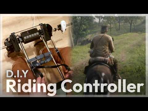
D.I.Y horse riding controller for the PC.
Openridingcontroller rev2 is an open-source printed circuit board by Squalius-cephalus, from the Squalius-cephalus/OpenRidingController repository on GitHub. It is a 2-layer board of 200 × 78.8 mm with 30 parts on 59 nets, routed with 316 tracks and 9 vias.
It is built around the TCRT5000 and RJ45. Its parts include 10 connectors, 6 resistors, 3 ICs and 1 switch. It belongs with the RP2040 boards of this library.
A horse riding game controller for the PC/Mac. The idea is to emulate basic horse riding behaviors and converts those to work a variety of video games.
The controller mainly uses RP2040 Zero, TCRT5000 IR modules and 3D printed parts. Code uses CircuitPython 10 for fast prototyping, later revisions may move to Arduino C or something similar.
Currently the controller can emulate keyboard, mouse and DirectInput controller, however, this wont work on any "keyboard to game console" adapter, because of how the USB composite system works.
Latest revision uses a PCB, and the goal is to minimize the number of 3D printed parts. Strirrups uses an IMU sensors, so controller can be adapted to different frames easily.
Build guide and BOM in the works.
Handwired design, frame, sensors etc uses many 3D printed parts. Not in active develoment.
| Qty | Value | Footprint | References |
|---|---|---|---|
| 4 | RJ45 | Connector_RJ:RJ45_OST_PJ012-8P8CX_Vertical | J2, J6, J9, J10 |
| 4 | SW_Push | Button_Switch_THT:SW_PUSH_6mm_H5mm | B_A1, B_B1, B_C1, B_D1 |
| 4 | VAL** | foot:mouse-bite-1mm-3mm | mouse-bite-1mm-3mm, mouse-bite-1mm-3mm, mouse-bite-1mm-3mm, mouse-bite-1mm-3mm |
| 2 | 10k | Resistor_THT:R_Axial_DIN0204_L3.6mm_D1.6mm_P7.62mm_Horizontal | R2, R4 |
| 2 | 22 | Resistor_THT:R_Axial_DIN0204_L3.6mm_D1.6mm_P7.62mm_Horizontal | R5, R6 |
| 2 | 330 | Resistor_THT:R_Axial_DIN0204_L3.6mm_D1.6mm_P7.62mm_Horizontal | R1, R3 |
| 2 | Conn_01x04_Socket | Connector_PinHeader_2.54mm:PinHeader_1x04_P2.54mm_Vertical | J3, J7 |
| 2 | MPU6050_Module | foot:MPU6050_Module | A1, A2 |
| 2 | TCRT5000 | foot:OPTO_TCRT5000 | U1, U2 |
| 1 | Conn_01x05_Socket | Connector_PinHeader_2.54mm:PinHeader_1x05_P2.54mm_Vertical | J8 |
| 1 | Conn_01x06 | foot:Nintendo_Wii_Peripheral_5Pin_Card_edge | J1 |
| 1 | OLED_128x64 | ScottoKeebs_Components:OLED_128x64 | J4 |
| 1 | RP2040_Zero | ScottoKeebs_MCU:RP2040_Zero | U3 |
| 1 | RotaryEncoder_Switch | Keebio-Parts.pretty-master:RotaryEncoder_Alps_EC11E-Switch_Vertical_H20mm | SW1 |
| 1 | USB_A | Connector_USB:USB_A_Molex_67643_Horizontal | J5 |
It measures 200 × 78.8 mm and has 2 copper layers, 1.6 mm thick.
30 parts, built around the TCRT5000 and RJ45. The full list of its parts is on this page, with links to each part's symbol and footprint where PCBKit's library has them.
From the Squalius-cephalus/OpenRidingController repository on GitHub, at the commit this page was made from: the board is kicad/rev2/openridingcontroller_rev2/rev2.kicad_pcb and its schematic kicad/rev2/openridingcontroller_rev2/rev2.kicad_sch. PCBKit opens the board in the browser, with nothing to install.
Its repository states no licence, so its author keeps all rights: ask Squalius-cephalus before reusing the design.

xtarke/automated_buggy
This shield connects microcontroller (MSP-EXP430FR2355) pins to the car's power board. Go to Power Board for more hardware information.

Amrlxyz/esp-lfr-buggy
2nd Year Embedded Systems Project (ESP) - Line Following Robot Buggy


ciiiutnfrc/eduromaa
Versión educativa del robot móvil RoMAA (EduRoMAA)

billtsol/Maze
This project demonstrates how to use an Arduino board, IR sensors, and a motor driver shield to create a maze-solving robot.

Potato-eater/Legacy2026
github repo for Robocup Junior Australia lightweight soccer team

2026MakerClub/PCB
projects with pcb, custom and commonly used schemes, footprints...etc.