
2 layers82 × 60 mm
Mdx1 ui
pingpongshow/MDX-1
Open multi-frequency + pulse-induction metal detector: KiCad hardware, search coil, portable-C firmware, iOS/Android apps. Experimental, unbuilt.
19 parts

Open multi-frequency + pulse-induction metal detector: KiCad hardware, search coil, portable-C firmware, iOS/Android apps. Experimental, unbuilt.
Mdx1 is an open-source printed circuit board by pingpongshow, from the pingpongshow/MDX-1 repository on GitHub. It is a 4-layer board of 135 × 92 mm with 325 parts on 352 nets, routed with 3,065 tracks and 1,020 vias.
It is built around the UCC27714D, BAS416 and SS34. Its parts include 121 capacitors, 100 resistors, 10 diodes, 4 ICs and 4 transistors.


An open, simultaneous multi-frequency + pulse-induction metal detector — hardware, search coil and firmware.
MDX-1 is a from-scratch detector design: a KiCad schematic and 4-layer main board, a 2-layer user-interface board, a hand-wound search coil, portable C firmware with a host simulator and test bench, and iOS/Android companion apps. The receive and transmit engine is specified around a coherent, DSP-first architecture:
Status: experimental, design stage
This is a paper design that has not been built or field-tested. The schematic is ERC-checked, the PCBs are placed and routed, the firmware core passes its host test bench, and the STM32 target layer is written against the CubeH7 HAL but has not run on hardware. Nothing here has been fabricated, assembled or measured. Component values, footprints and firmware behaviour may be wrong. Verify everything against the primary datasheets before ordering or building.
The transmit stage switches up to 100 V through an H-bridge into an inductive load. Treat it as a hazardous-voltage circuit: it can injure you and destroy parts if mis-built. Build and power it only if you are competent with high-voltage switching electronics.
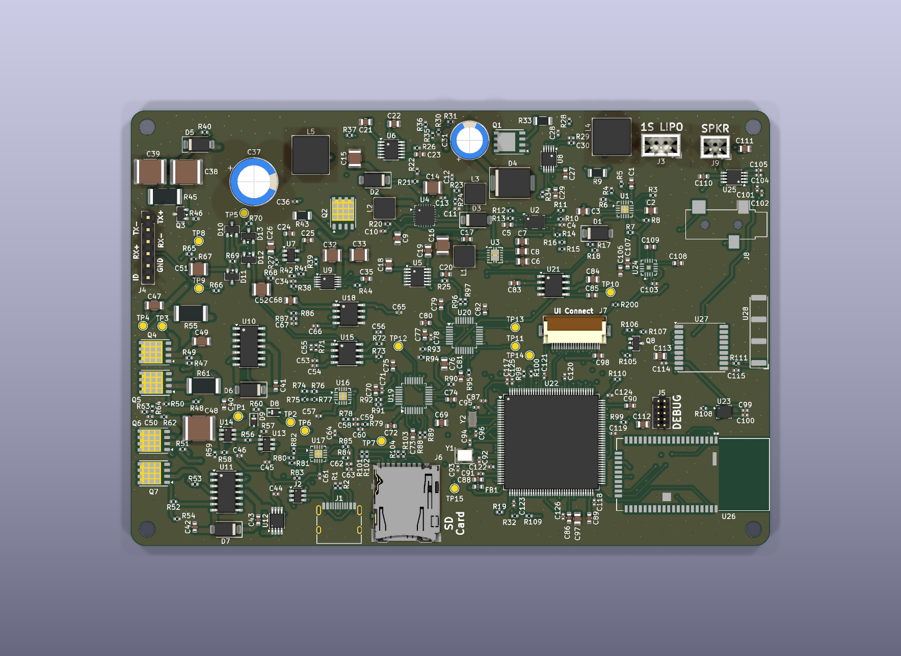
Main board, populated (3D view). Per-layer plots for both boards are in hardware/mdx1/images/.
| Path | What |
|---|---|
hardware/mdx1/mdx1.kicad_pro | KiCad project. Open this. |
hardware/mdx1/*.kicad_sch | Root sheet + hierarchical sheets (power, tx_driver, rx_frontend, adc, mcu, ui_audio_rf, coil). |
hardware/mdx1/mdx1.kicad_pcb | 135 × 92 mm 4-layer main board — footprints, nets, pours, routing, outline. |
hardware/mdx1/mdx1_ui.kicad_pcb | 82 × 60 mm 2-layer UI board (LCD, keypad, pinpoint trigger, power key, LEDs, front-light). |
hardware/mdx1/MDX*.kicad_sym, MDX.pretty/ | Project-local symbol/footprint libraries. |
hardware/mdx1/fab/ | Fabrication packages: Gerbers, drill, assembly BOM and pick-and-place for both boards (Gerbers/, BOM/, PNP/); interconnect BOM; enclosure DXFs (Case/). |
hardware/mdx1/images/ | Rendered board views: per-layer plots (copper, silkscreen) and a 3D top view of each board. |
firmware/ | Portable core (core/), host physics simulator + test bench (sim/), STM32H743 target layer (stm32/). make test runs the bench. |
app/ios/ | SwiftUI companion app (BLE): live status, on-detector menu, finds map, diagnostics; built-in demo detector. |
app/android/ | Kotlin/Compose port of the companion app. |
docs/MDX-1_design_report.html | Hardware design report. |
docs/MDX-1_coil_manual.html | Search-coil build manual and off-the-shelf coil path. |
docs/MDX-1_firmware_guide.html | Firmware guide with test evidence and screen renders. |
docs/MDX-1_assembly.md | Board population guide (build order, critical parts, mounting). |
docs/MDX-1_bringup.md | Staged first-power procedure — populate/verify one subsystem at a time. |
docs/MDX-1_link_protocol.md | Phone-link protocol (frames, item table, status packet, actions). |
docs/MDX-1_schematic.pdf | All schematic sheets. |
docs/datasheets/ | Third-party component datasheets used during the design review — not included in this repository (vendor copyright); part numbers are in the BOM under hardware/mdx1/fab/. |
tools/ | Design toolchain — see below. |
The KiCad schematic and boards are the source of truth — they are hand-placed and hand-routed. The remaining tools are read-only against the boards or operate on design inputs; none of them modify the .kicad_pcb / .kicad_sch files. (The original placement/schematic generators were removed to prevent accidental overwrites of the finished layout.)
| Tool | Purpose |
|---|---|
tools/fab_jlc.py | Reads the boards and writes the JLCPCB fabrication package: Gerbers + drill, assembly BOM and CPL for both boards. Does not modify the boards. |
tools/bom_data.json | Maintained part database (manufacturer part numbers, packages, pricing) read by fab_jlc.py and build_review.py. |
tools/tx_waveform_opt.py | Simulated-annealing optimiser for the 3-level, 5-line transmit waveform → tx_waveform.json. |
tools/coil_calc.py | Coil electromagnetics (Neumann self/mutual inductance, null geometry, field) → coil_calc.json. |
tools/build_review.py, build_coil_manual.py | Regenerate the BOM-review and coil-manual documents under docs/. |
tools/gen_fonts.py, pbm2png.py | LCD bitmap fonts; simulator screen-render conversion. |
To regenerate the fabrication package after any board change (from KiCad's bundled Python):
/Applications/KiCad/KiCad.app/Contents/Frameworks/Python.framework/Versions/Current/bin/python3 tools/fab_jlc.pycd firmware
make test # build the portable core against the host simulator and run the test bench
make screens # render the UI screens from the simulatorThe core (firmware/core/) is target-independent C: DSP, detector logic, UI, phone link, audio. The simulator (firmware/sim/) provides a synthetic coil/target/ground model so the whole signal chain runs and is tested on a desktop. The STM32 layer (firmware/stm32/) maps the core onto the H743 peripherals.
docs/datasheets/.Copyright © 2026 Stephen Packer.
This project — hardware, search-coil design, firmware, apps and documentation — is licensed under the Creative Commons Attribution-NonCommercial 4.0 International License (CC BY-NC 4.0). See LICENSE for the full text.
In short, you are free to share and adapt the material for non-commercial purposes, as long as you give appropriate credit. Commercial use is not permitted without separate written permission from the copyright holder.
Note: CC licenses are not designed specifically for software. CC BY-NC 4.0 is applied here to express a single non-commercial intent across the whole project (hardware, firmware and docs together). For commercial licensing of any part, contact the author.
Provided as-is, with no warranty. This is an unbuilt, untested hobby design involving hazardous voltages. You are responsible for verifying correctness and safety before building or powering anything. Comply with the radio-emissions and other regulations in your jurisdiction before operating a transmitter of any kind.
| Qty | Value | Footprint | References |
|---|---|---|---|
| 29 | 100n | Capacitor_SMD:C_0402_1005Metric | C4, C10, C28, C44, C45, C100, C114, C117, C118, C119, C120, C121, C122, C123, C124, C125 +13 |
| 20 | 1u | Capacitor_SMD:C_0603_1608Metric | C5, C24, C25, C70, C72, C73, C74, C75, C77, C79, C80, C81, C82, C108, C109, C110 +4 |
| 13 | 10k | Resistor_SMD:R_0402_1005Metric | R10, R11, R16, R19, R37, R49, R50, R53, R54, R60, R64, R98, R200 |
| 10 | 100k | Resistor_SMD:R_0402_1005Metric | R7, R8, R14, R15, R24, R46, R69, R70, R107, R110 |
| 10 | 1k 0.1% | Resistor_SMD:R_0402_1005Metric | R71, R72, R74, R75, R76, R77, R80, R81, R82, R83 |
| 8 | 10u | Capacitor_SMD:C_0805_2012Metric | C68, C69, C76, C84, C97, C111, C112, C113 |
| 6 | 47k | Resistor_SMD:R_0402_1005Metric | R17, R36, R101, R102, R103, R104 |
| 5 | 100R | Resistor_SMD:R_0402_1005Metric | R78, R79, R84, R85, R106 |
| 5 | 10u 10V | Capacitor_SMD:C_0805_2012Metric | C2, C3, C6, C9, C26 |
| 5 | 4u7 | Capacitor_SMD:C_0603_1608Metric | C20, C23, C29, C35, C86 |
| 4 | 1M | Resistor_SMD:R_0402_1005Metric | R21, R62, R67, R68 |
| 4 | 220n | Capacitor_SMD:C_0402_1005Metric | C11, C34, C104, C105 |
| 4 | 22k | Resistor_SMD:R_0402_1005Metric | R18, R29, R39, R63 |
| 4 | 2u2 | Capacitor_SMD:C_0603_1608Metric | C89, C90, C106, C107 |
| 4 | 330p C0G | Capacitor_SMD:C_0402_1005Metric | C59, C60, C63, C64 |
| 4 | 4R7 | Resistor_SMD:R_0402_1005Metric | R47, R48, R51, R52 |
| 4 | BAS416 | Package_TO_SOT_SMD:SOT-23 | D10, D11, D12, D13 |
| 4 | BSC320N20NS3 G | Package_SON:Infineon_PG-TDSON-8_6.15x5.15mm | Q4, Q5, Q6, Q7 |
| 4 | MountingHole_3.2mm_M3 | MountingHole_3.2mm_M3 | H1, H2, H3, H4 |
| 3 | 1u | Capacitor_SMD:C_0402_1005Metric | C67, C102, C103 |
| 3 | 1u 25V | Capacitor_SMD:C_0603_1608Metric | C17, C40, C42 |
| 3 | 22u 25V | Capacitor_SMD:C_1210_3225Metric | C14, C15, C16 |
| 3 | 2u2 250V | Capacitor_SMD:C_2220_5750Metric | C38, C39, C48 |
| 3 | 4k7 | Resistor_SMD:R_0402_1005Metric | R12, R13, R109 |
| 2 | 100k (FORMAT=1 frame-sync) | Resistor_SMD:R_0402_1005Metric | R91, R96 |
| 2 | 100k (FSMODE=0 slave) | Resistor_SMD:R_0402_1005Metric | R90, R95 |
| 2 | 100k (HR=1) | Resistor_SMD:R_0402_1005Metric | R92, R97 |
| 2 | 10R | Resistor_SMD:R_0402_1005Metric | R34, R44 |
| 2 | 10k (int LDO) | Resistor_SMD:R_0402_1005Metric | R89, R94 |
| 2 | 10p C0G | Capacitor_SMD:C_0402_1005Metric | C93, C94 |
| 2 | 10u 25V | Capacitor_SMD:C_0805_2012Metric | C19, C22 |
| 2 | 1k | Resistor_SMD:R_0402_1005Metric | R56, R59 |
| 2 | 1u C0G/film | Capacitor_SMD:C_1210_3225Metric | C51, C52 |
| 2 | 220n 50V | Capacitor_SMD:C_0603_1608Metric | C41, C43 |
| 2 | 22u 6.3V | Capacitor_SMD:C_0805_2012Metric | C7, C8 |
| 2 | 3n3 C0G | Capacitor_SMD:C_0402_1005Metric | C58, C62 |
| 2 | 442k | Resistor_SMD:R_0402_1005Metric | R30, R35 |
| 2 | 47R | Resistor_SMD:R_0402_1005Metric | R65, R66 |
| 2 | 49k9 0.1% SET (100uA) | Resistor_SMD:R_0402_1005Metric | R25, R26 |
| 2 | 4n7 | Capacitor_SMD:C_0402_1005Metric | C30, C101 |
| 2 | 4u7 10V | Capacitor_SMD:C_0603_1608Metric | C1, C27 |
| 2 | 4u7 25V | Capacitor_SMD:C_0805_2012Metric | C18, C21 |
| 2 | 4u7 XAL4020 | Inductor_SMD:L_Coilcraft_XAL4020-XXX | L2, L3 |
| 2 | 5k1 | Resistor_SMD:R_0402_1005Metric | R1, R2 |
| 2 | 6.8p C0G | Capacitor_SMD:C_0402_1005Metric | C95, C96 |
| 2 | 60k4 (HR mode) | Resistor_SMD:R_0402_1005Metric | R88, R93 |
| 2 | 619k | Resistor_SMD:R_0402_1005Metric | R40, R41 |
| 2 | 680p C0G | Capacitor_SMD:C_0402_1005Metric | C55, C56 |
| 2 | 9k1 | Resistor_SMD:R_0402_1005Metric | R57, R58 |
| 2 | NSVBAT54SWT1G | Package_TO_SOT_SMD:SOT-323_SC-70 | D8, D9 |
| 2 | SS34 | Diode_SMD:D_SMA | D2, D3 |
| 2 | THS4551 (G=1) | Package_DFN_QFN:VQFN-16-1EP_3x3mm_P0.5mm_EP1.68x1.68mm | U16, U17 |
| 2 | UCC27714D | Package_SO:SOIC-14_3.9x8.7mm_P1.27mm | U10, U11 |
| 2 | US1D (200V fast) | Diode_SMD:D_SMA | D6, D7 |
| 1 | 0R (addr) | Resistor_SMD:R_0402_1005Metric | R108 |
| 1 | 100R (VIN filter) | Resistor_SMD:R_0402_1005Metric | R20 |
| 1 | 100n 250V | Capacitor_SMD:C_1206_3216Metric | C49 |
| 1 | 100u 50V | Capacitor_THT:CP_Radial_D8.0mm_P3.50mm | C31 |
| 1 | 105R 0.1% (Rg) | Resistor_SMD:R_0402_1005Metric | R73 |
| 1 | 10R (LCD supply) | Resistor_SMD:R_0402_1005Metric | R27 |
| 1 | 10k (TS, DNP w/ NTC) | Resistor_SMD:R_0402_1005Metric | R6 |
| 1 | 10k 0.1% | Resistor_SMD:R_0402_1005Metric | R87 |
| 1 | 10k 1W (bleed) | Resistor_SMD:R_2512_6332Metric | R45 |
| 1 | 10m 1% (gauge) | Resistor_SMD:R_1206_3216Metric | R9 |
| 1 | 10n | Capacitor_SMD:C_0402_1005Metric | C36 |
| 1 | 10n (CP) | Capacitor_SMD:C_0402_1005Metric | C12 |
| 1 | 10nF | Capacitor_SMD:C_0402_1005Metric | C128 |
| 1 | 10u 50V | Capacitor_SMD:C_1210_3225Metric | C32 |
| 1 | 113k | Resistor_SMD:R_0402_1005Metric | R22 |
| 1 | 140k (100kHz) | Resistor_SMD:R_0402_1005Metric | R38 |
| 1 | 16.384 MHz 3225 | Crystal:Crystal_SMD_3225-4Pin_3.2x2.5mm | Y1 |
| 1 | 1k1 (IIN 1.4A) | Resistor_SMD:R_0402_1005Metric | R3 |
| 1 | 1n | Capacitor_SMD:C_0402_1005Metric | C50 |
| 1 | 1n 250V | Capacitor_SMD:C_1206_3216Metric | C47 |
| 1 | 1u5 XAL4020 | Inductor_SMD:L_Coilcraft_XAL4020-XXX | L1 |
| 1 | 20k0 | Resistor_SMD:R_0402_1005Metric | R42 |
| 1 | 20m (sense) | Resistor_SMD:R_1206_3216Metric | R33 |
| 1 | 20m 1% shunt | Resistor_SMD:R_2512_6332Metric | R55 |
| 1 | 22R | Resistor_SMD:R_0402_1005Metric | R105 |
| 1 | 22u XAL7050 | Inductor_SMD:L_Coilcraft_XAL7050-XXX | L4 |
The 248 most common of 325 parts.
pingpongshow/MDX-1
Open multi-frequency + pulse-induction metal detector: KiCad hardware, search coil, portable-C firmware, iOS/Android apps. Experimental, unbuilt.

jreeve-nl/led-supply
Nice power factor corrected switching LED lighting driver.


manvalan/MuonScope
Piano di rivelazione MuonScope con 16 fotodiodi VBPW34S in matrice 4×4 a passo 10 mm, per il bus MIKILAB REV5.1.


willem-pennings/balancing-cube
A cube that balances itself in a corner or edge using reaction wheels

Arrow-air/project-quiver
Project Quiver documentation, designs, and project artifacts.

It measures 135 × 92 mm and has 4 copper layers, 1.6 mm thick.
325 parts, built around the UCC27714D, BAS416 and SS34. The full list of its parts is on this page, with links to each part's symbol and footprint where PCBKit's library has them.
From the pingpongshow/MDX-1 repository on GitHub, at the commit this page was made from: the board is hardware/mdx1/mdx1.kicad_pcb and its schematic hardware/mdx1/adc.kicad_sch. PCBKit opens the board in the browser, with nothing to install.
Its repository states no licence, so its author keeps all rights: ask pingpongshow before reusing the design.