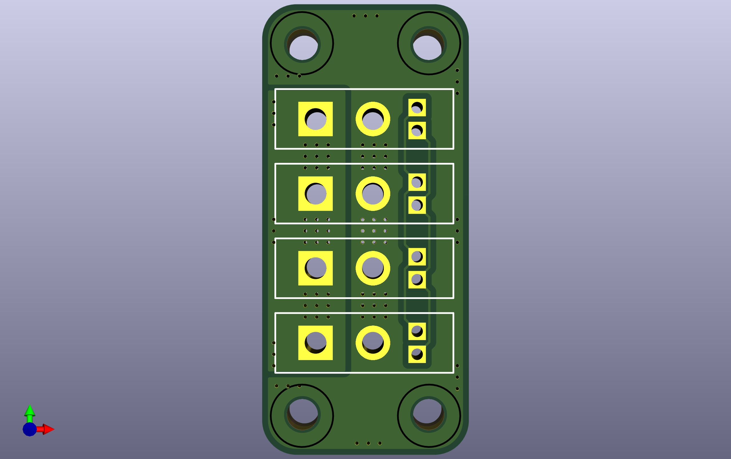
Pineapple V3 Robot PCB — Basic
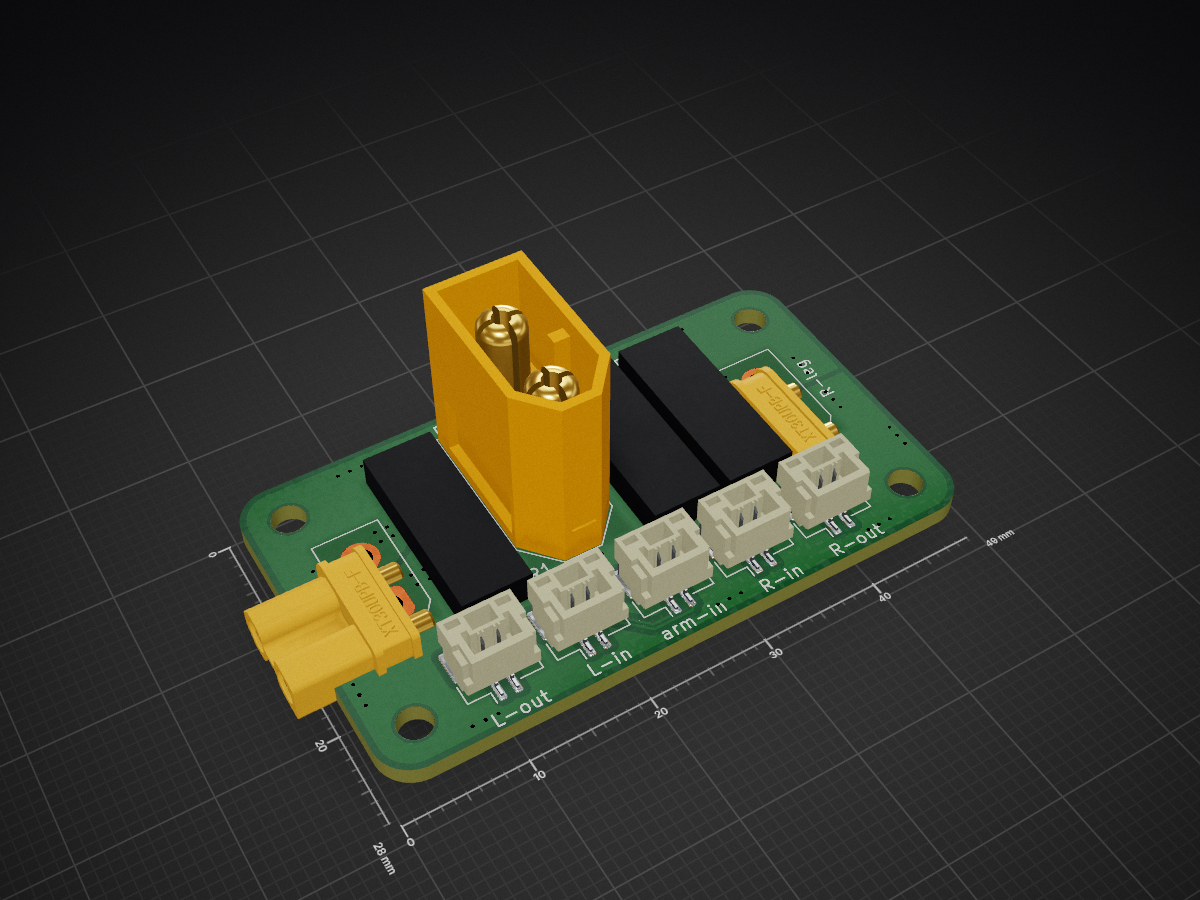
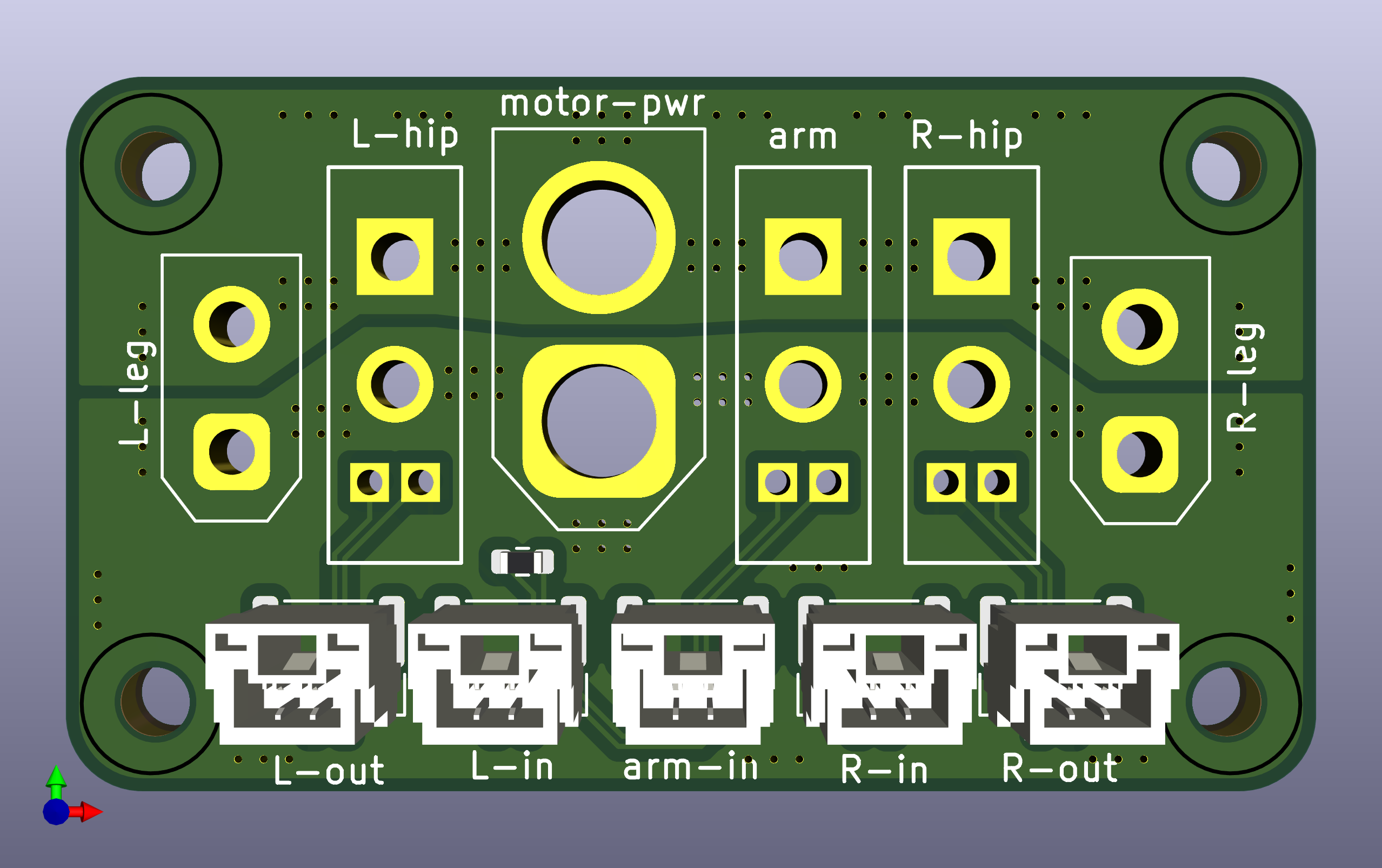
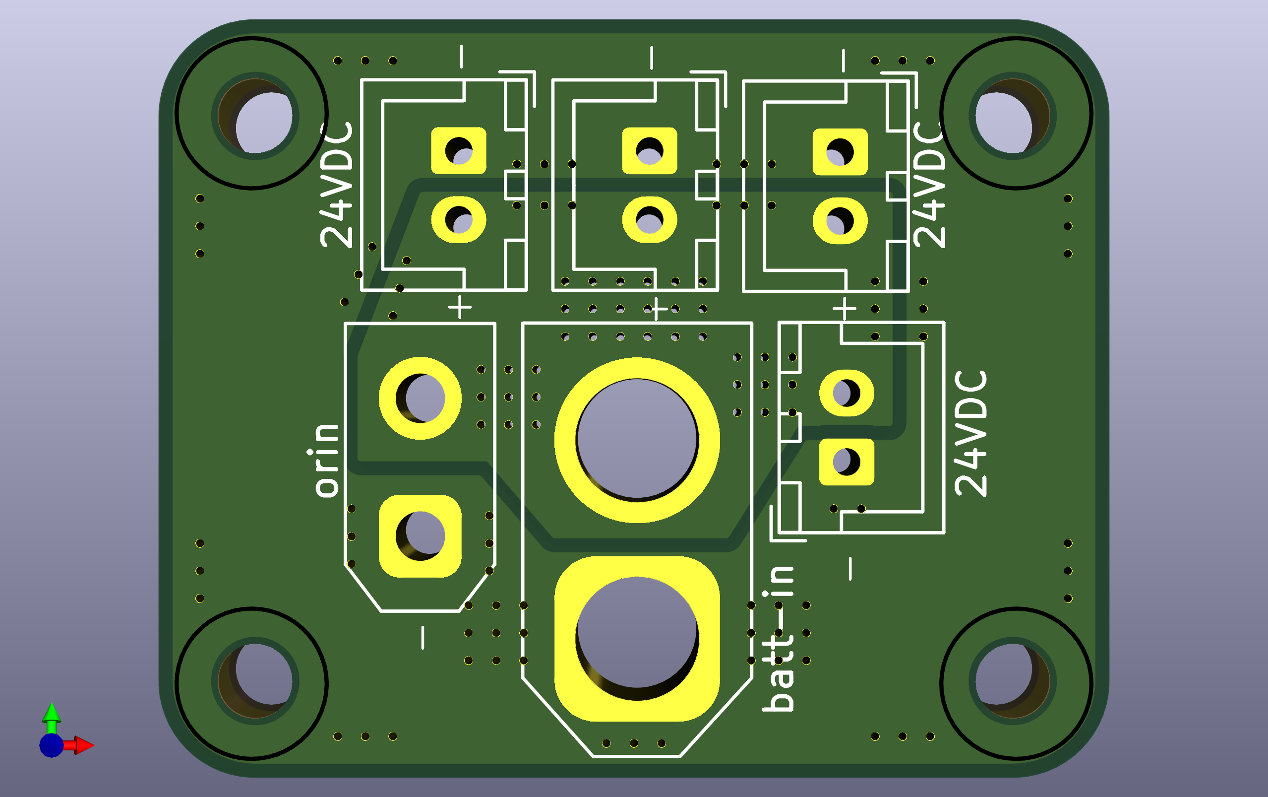
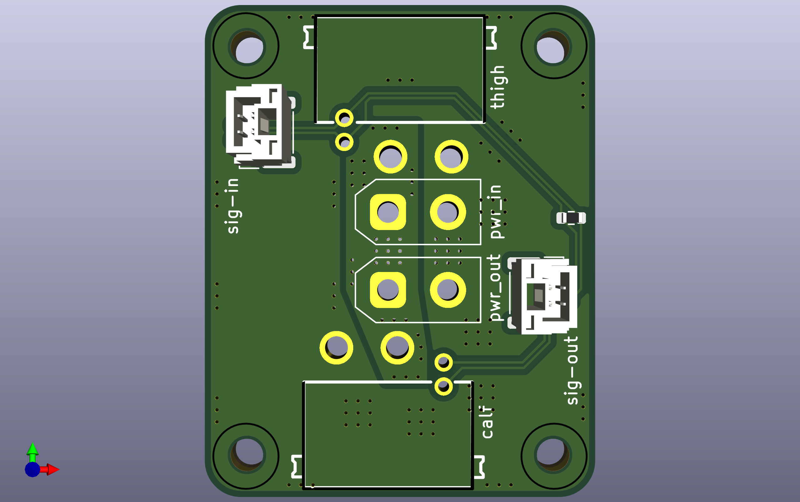
Basic (simplified) version of the Pineapple V3 robot PCBs. The leg IMU is simplified, so this build drops the separate calf board and uses fewer signal headers than the full version. Four boards total: base, base_A, thigh, and arm. Each board has its own folder containing the .kicad_pcb, .kicad_sch, and project files.
Exported Gerber files (ready for fabrication) are in the Gerbers/ folder — one _gbr.zip per board.
Jump to: Wiring Diagram · Soldering Tips
Boards
PCB Specifications
| Item | Spec |
|---|
| Layers | 2 |
| Thickness | 1.6 mm |
| Copper weight | 1 oz |
Bill of Materials
(Ordering at least double the quantity is recommended.)
Combined total (full robot: base ×1, base_A ×1, thigh ×2, arm ×2)
XT Series connector
| Image | Footprint | Quantity | Note | Link |
|---|
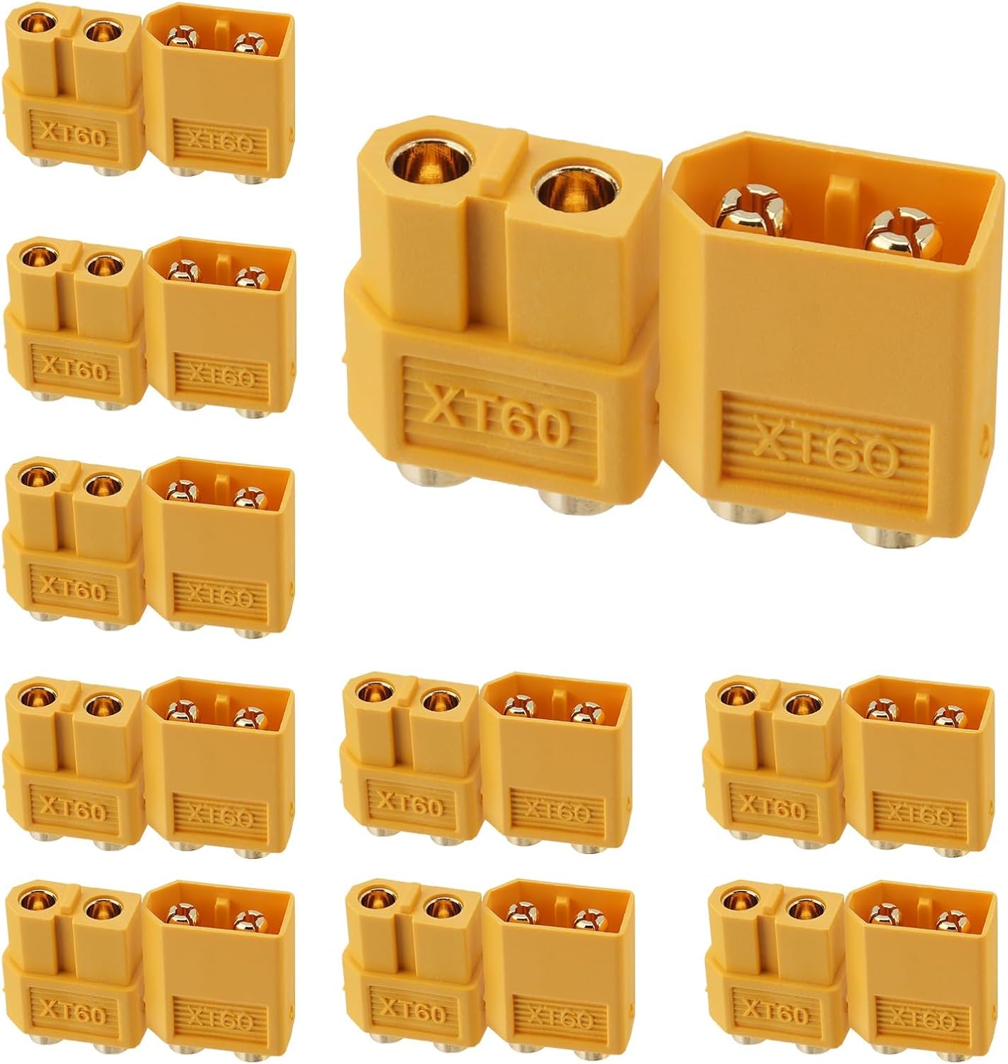 | AMASS_XT60-M_1x02_P7.20mm_Vertical | 2 | XT60 male, vertical | Buy |
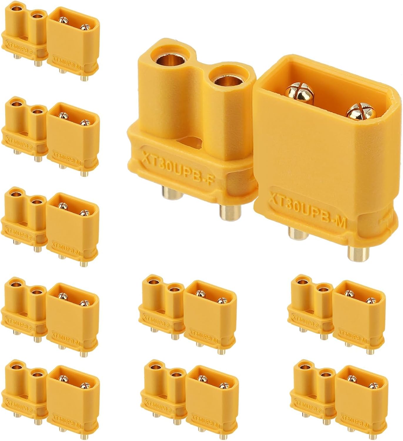 | AMASS_XT30UPB-F_1x02_P5.0mm_Vertical | 5 | XT30 female, vertical board mount | Buy |
| AMASS_XT30UPB-M_1x02_P5.0mm_Vertical | 2 | XT30 male, vertical board mount | Buy |
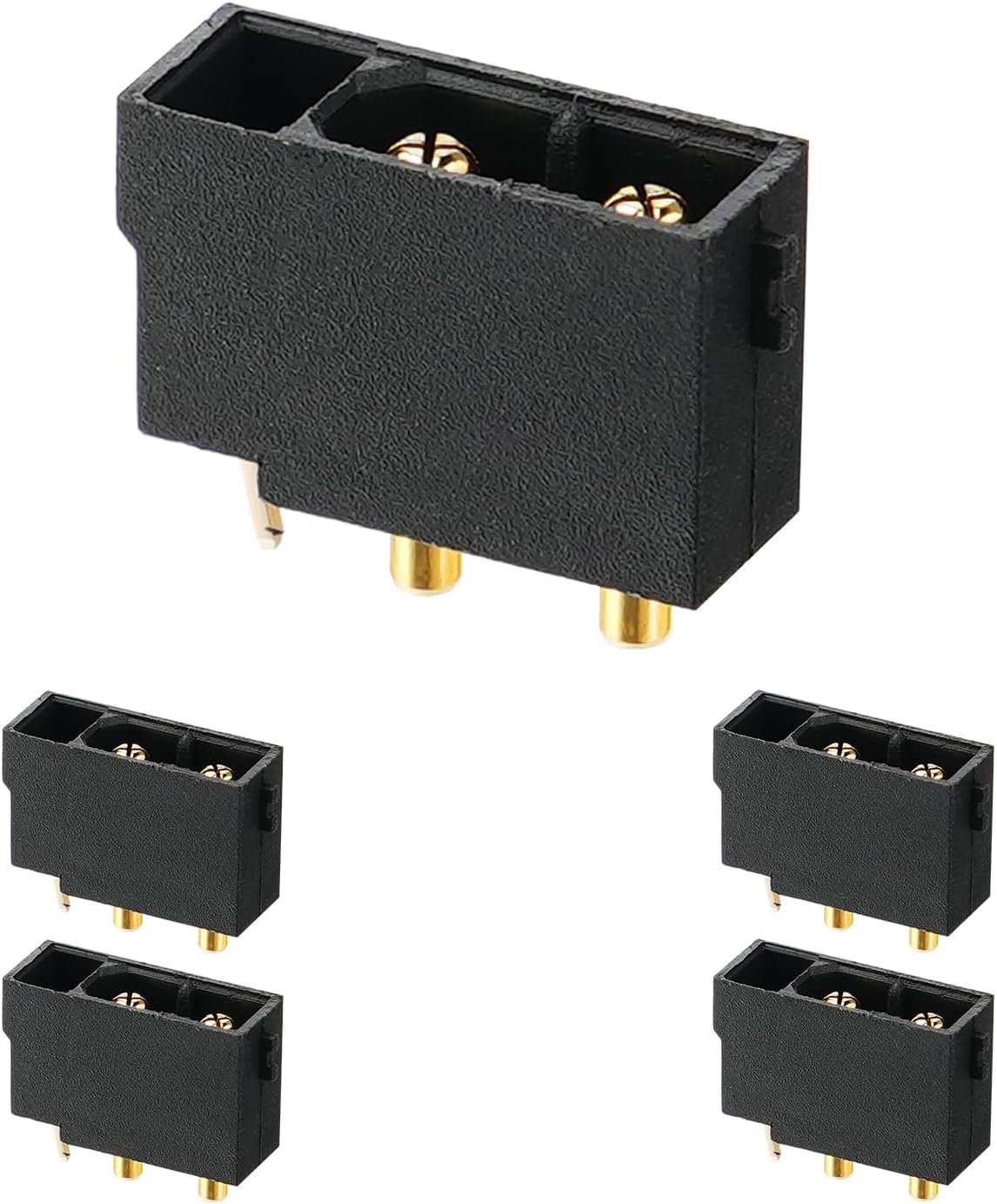 | XT30_22_M_vertical | 11 | XT30 2+2 (power+signal) male, vertical | Buy |
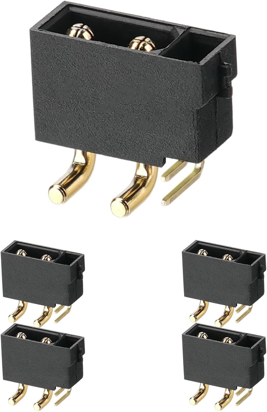 | CONN-TH_4P-XT30PW-M | 4 | XT30 2+2 (power+signal) male, horizontal | Buy |
JST XH2.5 connector
| Image | Footprint | Quantity | Note | Link |
|---|
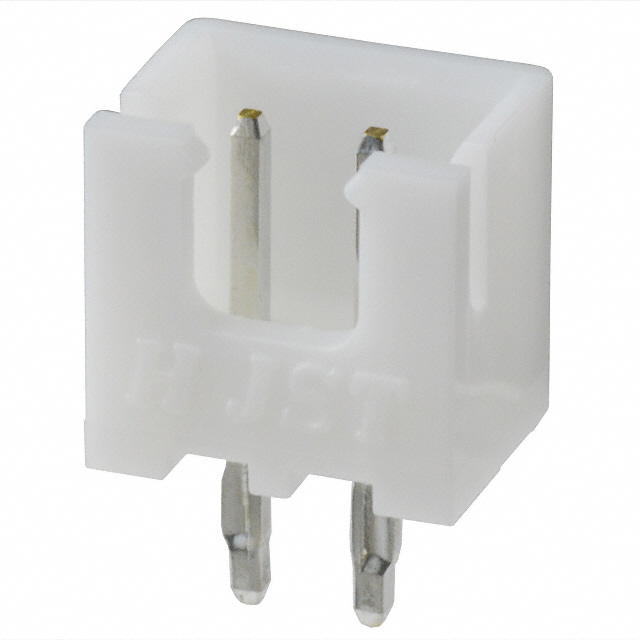 | JST_XH_B2B-XH-A_1x02_P2.50mm_Vertical | 4 | JST XH 2-pin, 2.5 mm pitch, vertical | Buy |
JST GH1.25 Header
| Image | Footprint | Quantity | Note | Link |
|---|
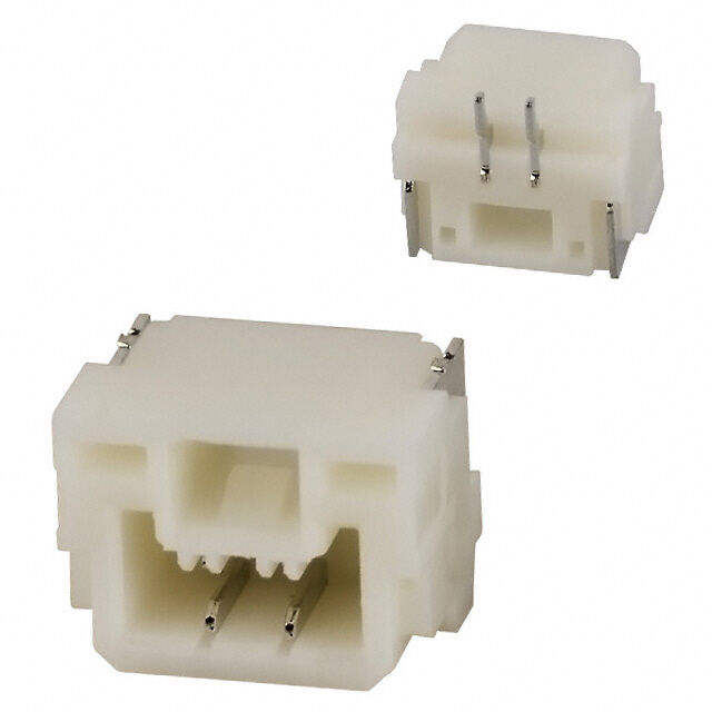 | JST_GH_BM02B-GHS-TBT_1x02-1MP_P1.25mm_Vertical | 9 | JST GH 2-pin, 1.25 mm pitch, vertical SMD | Buy |
0603 SMD Resistor
| Image | Footprint | Quantity | Note | Link |
|---|
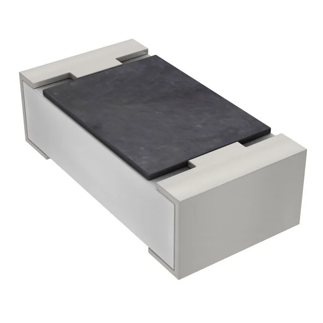 | R_0603_1608Metric | 3 | 0603 SMD resistor, 120 Ω, CAN bus termination | Buy |
Mounting hardware
| Image | Footprint | Quantity | Note | Link |
|---|
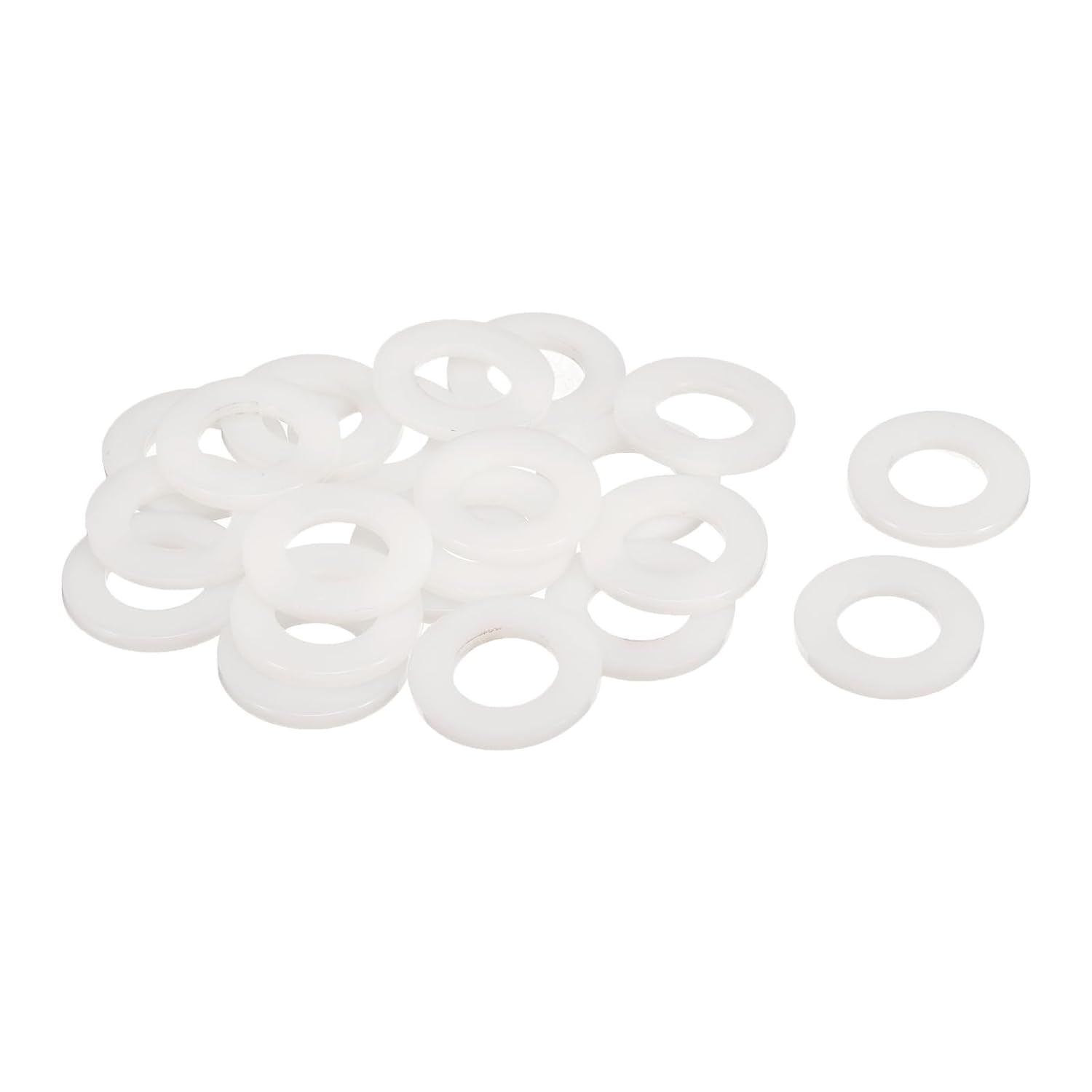 | Plastic ring (nylon washer, M2.5) | 24 | Insulating plastic ring around each mounting hole | Buy |
Per board
pineapple_v3_base (×1)
| Footprint | Quantity | Note |
|---|
| AMASS_XT60-M_1x02_P7.20mm_Vertical | 1 | XT60 male, vertical |
| AMASS_XT30UPB-F_1x02_P5.0mm_Vertical | 2 | XT30 female, vertical board mount |
| XT30_22_M_vertical | 3 | XT30 2+2 (power+signal) male, vertical |
| JST_GH_BM02B-GHS-TBT_1x02-1MP_P1.25mm_Vertical | 5 | JST GH 2-pin, 1.25 mm pitch, vertical SMD |
| R_0603_1608Metric | 1 | 0603 SMD resistor, 120 Ω, CAN bus termination |
| Plastic ring (nylon washer, M2.5) | 4 | Insulating plastic ring around each mounting hole |
pineapple_v3_base_A (×1)
| Footprint | Quantity | Note |
|---|
| AMASS_XT60-M_1x02_P7.20mm_Vertical | 1 | XT60 male, vertical |
| AMASS_XT30UPB-F_1x02_P5.0mm_Vertical | 1 | XT30 female, vertical board mount |
| JST_XH_B2B-XH-A_1x02_P2.50mm_Vertical | 4 | JST XH 2-pin, 2.5 mm pitch, vertical |
| Plastic ring (nylon washer, M2.5) | 4 | Insulating plastic ring around each mounting hole |
pineapple_v3_thigh (×2)
| Footprint | Quantity (per board) | Note |
|---|
| AMASS_XT30UPB-F_1x02_P5.0mm_Vertical | 1 | XT30 female, vertical board mount |
| AMASS_XT30UPB-M_1x02_P5.0mm_Vertical | 1 | XT30 male, vertical board mount |
| CONN-TH_4P-XT30PW-M | 2 | XT30 2+2 (power+signal) male, horizontal |
| JST_GH_BM02B-GHS-TBT_1x02-1MP_P1.25mm_Vertical | 2 | JST GH 2-pin, 1.25 mm pitch, vertical SMD |
| R_0603_1608Metric | 1 | 0603 SMD resistor, 120 Ω, CAN bus termination |
| Plastic ring (nylon washer, M2.5) | 4 | Insulating plastic ring around each mounting hole |
pineapple_v3_arm (×2)
| Footprint | Quantity (per board) | Note |
|---|
| XT30_22_M_vertical | 4 | XT30 2+2 (power+signal) male, vertical |
| Plastic ring (nylon washer, M2.5) | 4 | Insulating plastic ring around each mounting hole |
Soldering Tips
- The POWER pins (24V, GND) lose heat fast, so heat them with the iron for longer than usual. Check carefully that the solder joint isn't loose or incomplete.
- Always use the plastic ring before putting in the screw. Without it, the screw can scratch the surface and cause a short circuit.
- Solder the small parts first, then move to the bigger ones: resistor → GH → XH → horizontal XT30 → vertical XT30 → XT60.
- Before connecting the battery, use a multimeter to check that 24V and GND are not shorted.
Cable-Side Connectors & Wire
Mating (cable-side) connectors for the board-mounted headers above, bought separately from the wire. (Ordering at least double the quantity is recommended.)
XT Series connector
| Model | Quantity | Link |
|---|
| Amass XT60 M/F pairs | 2 | Buy |
| Amass XT30U M/F pairs | 4 | Buy |
| Amass XT30(2+2) Female | 40 | Buy |
JST XH2.5 connector
| Model | Quantity | Link |
|---|
| XHP-2 (Female Housing) | 8 | Buy |
| SXH-001T-P0.6N (Female Pin) | 16 | Buy |
JST GH1.25 connector
| Model | Quantity | Link |
|---|
| GHR-02V-S (Female Housing) | 18 | Buy |
| SSHL-002T-P0.2 (Female Pin) | 36 | Buy |
Wire
| Model | Used for | Link |
|---|
| 12AWG Silicone Wire | XT60 | Buy |
| 16AWG Silicone Wire | XT30 / XT30(2+2) power pins | Buy |
| 22AWG Silicone Wire | XT30(2+2) signal pins / JST XH2.5 | Buy |
| 28AWG Silicone Wire | JST GH1.25 | Buy |
Additional Components
(Quantities below are placeholders — confirm against the actual design before ordering.)
| Model | Quantity | Note | Link |
|---|
| KWONONG LED Latching Push Button Switch, 16mm, White, IP67, 5–24V 20A 1NO, with wire socket plug | 1 | Panel-mount illuminated button | Buy |
| 16mm Latching Emergency Stop Push Button, Mushroom Head, Stainless Steel Red, SPDT 1NO 1NC, with wired socket | 1 | E-stop switch | Buy |
| HiLetgo 1-Channel 5V 30A Relay Module, Optocoupler Isolation, High/Low Trigger | 1 | 2-pack per listing | Buy |
| chenyang USB-C DIY Connector, USB 3.1 Type C 24-Pin Male Plug, Solder Adapter with PCB Board | 1 | 10-pack per listing | Buy |