2 layers60 × 30 mm
Controller
google/mozc-devices
Circuit diagrams and firmware source code for Gboard DIY keyboards
11 parts3kApache-2.0
 pierrotm777/MultiDecoderCoder5
Decoder PPM, SBUS, IBUS, and more
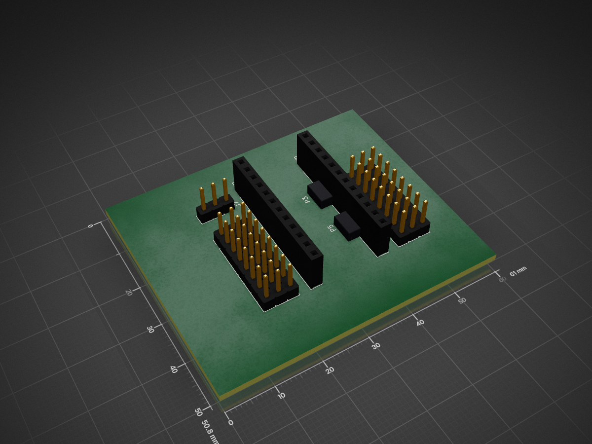
MultiDecoderCoder is an open-source printed circuit board by pierrotm777, from the pierrotm777/MultiDecoderCoder repository on GitHub. It is a 2-layer board of 61 × 50.8 mm with 11 parts on 19 nets.
This code is running only with Arduino Uno,Pro Mini ou Pro Micro - Option JetiEx is running only with Pro Micro - Option Failsafe is running only with Pro Mini
Decoder for maxi 16 servos for signals protols:
Coder convert 8 outputs servos PWM in:
How to use it: When you use your module the first time, you need to configure it. For that, you need to connect FTDI module to your Pro Mini board or use the USB port of your Pro Micro board. Use the IDE console (115200 bauds and NL and CR). You have 3 secondes for use the ENTER key. After that, without new settings, the code start in PPM mode.
The console will return:
Version:0.40
Wait Return...

Starting without configuration
Decoder in use
Failsafe is Off
8 outputs mode (Use D2-D9)
PPM mode in use
If you use the ENTER key before the 3s, you enter in the Configuration mode.
Version:0.40
Wait Return.

Configuration mode is actived
Decoder in use
Failsafe is Off
8 outputs mode (Use D2-D9)
PPM mode in use
Enter 'h' key (without cote) for the help.
h Help
q quit
0 set Decoder mode
1 set Coder mode
n set 8/16 outputs mode
r first 8 outputs changed
p set PPM mode
s set SBUS mode
i set IBUS mode
d set DSMX mode
m set SRLX mode
u set SUMD mode
j set JETIEx mode
f set Failsafe values
The DECODER mode know the protocols PPM, SBUS, IBUS, DSMX, SRLX, SUMD and JETIEx (Pro Micro only). The CODER mode know the protocols PPM and SBUS only.
How to connect your module:
| Qty | Value | Footprint | References |
|---|---|---|---|
| 2 | ADC | Socket_Arduino_Pro_Mini:Socket_Strip_Arduino_1x02 | P3, P5 |
| 1 | Analog | Connector_PinSocket_2.54mm:PinSocket_1x12_P2.54mm_Vertical | P4 |
| 1 | Ch1_8 | Connector_PinHeader_2.54mm:PinHeader_1x08_P2.54mm_Vertical | J1 |
| 1 | Ch1_8V+ | Connector_PinHeader_2.54mm:PinHeader_1x08_P2.54mm_Vertical | J2 |
| 1 | Ch1_8V- | Connector_PinHeader_2.54mm:PinHeader_1x08_P2.54mm_Vertical | J3 |
| 1 | Ch9_16 | Connector_PinHeader_2.54mm:PinHeader_1x08_P2.54mm_Vertical | J4 |
| 1 | Ch9_16V+ | Connector_PinHeader_2.54mm:PinHeader_1x08_P2.54mm_Vertical | J5 |
| 1 | Ch9_16V- | Connector_PinHeader_2.54mm:PinHeader_1x08_P2.54mm_Vertical | J6 |
| 1 | Conn_01x03 | Connector_PinHeader_2.54mm:PinHeader_1x03_P2.54mm_Vertical | J7 |
| 1 | Digital | Connector_PinSocket_2.54mm:PinSocket_1x12_P2.54mm_Vertical | P1 |
It measures 61 × 50.8 mm and has 2 copper layers, 1.6 mm thick.
11 parts. The full list of its parts is on this page, with links to each part's symbol and footprint where PCBKit's library has them.
From the pierrotm777/MultiDecoderCoder repository on GitHub, at the commit this page was made from: the board is PCB/MultiDecoderCoder.kicad_pcb. PCBKit opens the board in the browser, with nothing to install.
Its repository states no licence, so its author keeps all rights: ask pierrotm777 before reusing the design.
google/mozc-devices
Circuit diagrams and firmware source code for Gboard DIY keyboards


FrameworkComputer/ExpansionCards
Reference designs and documentation to create Expansion Cards for the Framework Laptop

hoglet67/RGBtoHDMI
Bare-metal Raspberry Pi project that provides pixel-perfect sampling of Retro Computer RGB/YUV video and conversion to HDMI

hackclub/OnBoard
💡 Join 1,000 teenagers and make your first PCB with a $100 grant!


tardate/LittleArduinoProjects
a collection of "Little Electronic & Arduino Projects", most involving electronics or an Arduino in one way or another!

basilfx/TRADFRI-Hacking
Hacking IKEA TRÅDFRI products, such as light bulbs, window blinds and other accessories.