
4 layers68.6 × 53.3 mm

 phampaul07/Pomodoro-Cube1
A fully custom embedded productivity cube featuring a Pomodoro timer, digital clock, virtual pet, productivity tracker, and magnetic charging dock.
Pomodoro Timer is an open-source printed circuit board by phampaul07, from the phampaul07/Pomodoro-Cube repository on GitHub, published under the MIT licence. It is a 2-layer board of 53.5 × 53.5 mm with 20 parts on 19 nets, routed with 225 tracks and 0 vias.
It is built around the DS3231S#. Its parts include 8 connectors, 5 capacitors, 2 resistors and 1 switch.
CircuitPython • ESP32-C3 • Embedded Systems • CAD • 3D Printing • Analog Electronics • KiCad
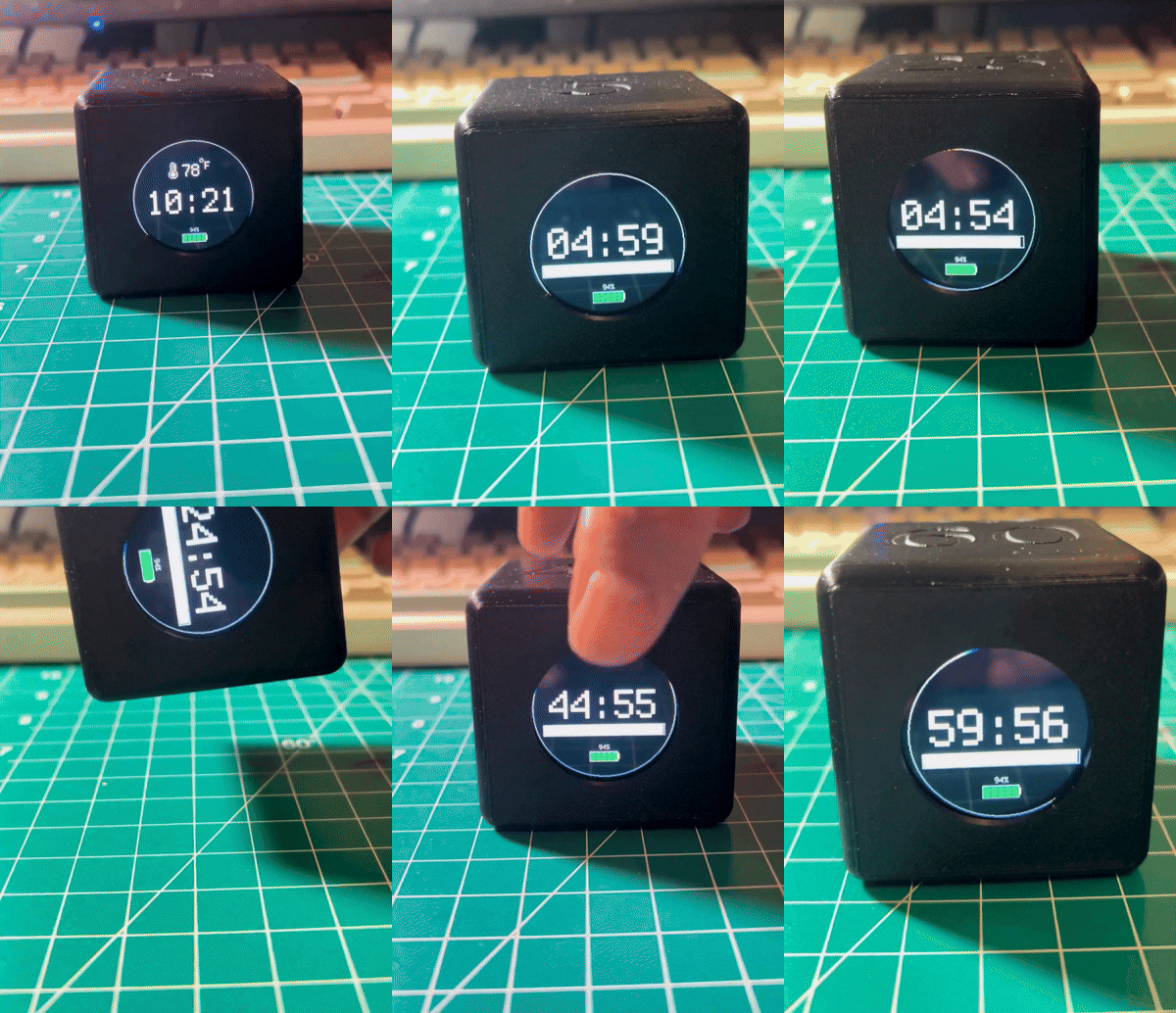
The Smart Pomodoro Cube is a handheld productivity device that combines embedded systems, hardware engineering, and industrial design into a compact form factor no larger than a standard Rubik's Cube.
Instead of navigating through menus or using a touchscreen, the cube uses its physical orientation to select timer durations. Once docked onto its custom magnetic charging station, it transforms into an entirely different interface featuring an interactive virtual pet, productivity tracker, and quick-access study tools.
Every major component—including the enclosure, charging dock, firmware, custom KiCad PCB, and user interface—was designed specifically for this project.
The goal was not only to create a useful studying companion, but also to explore embedded systems, custom electronics, CAD, and hardware-software integration while fitting everything inside an extremely limited volume.
The Pomodoro Cube has two primary modes of operation.

Click the thumbnail above to watch the standalone demonstration.

Click the thumbnail above to watch the dock demonstration.
When idle, the cube functions as a portable desk clock displaying:
using an external RTC module and onboard sensors.
The cube's primary function is a distraction-free Pomodoro timer.
Simply rotate the cube onto one of its faces to instantly choose a timer duration.
Features include:
One of the biggest design goals was eliminating cables during normal use.
The cube charges magnetically using pogo pins while simultaneously detecting dock states and reading dock button presses.
The charging dock was hand-built using a custom perfboard and soldered circuitry, while the internal electronics of the cube itself are mounted on a custom-designed PCB routed in KiCad.
Docking the cube unlocks four additional operating modes.
Displays the standard clock while charging.
Instantly adds study time in 15-minute increments without rotating the cube.
An interactive Tamagotchi-inspired virtual pet.
Features include:
Tracks long-term study habits including:
| Component | Purpose |
|---|---|
| Seeed Studio XIAO ESP32-C3 | Main Microcontroller |
| Custom KiCad PCB | Main Board / Cube Electronics |
| 1.28" Round GC9A01 IPS Display | User Interface |
| MPU6050 | Orientation Detection |
| RTC Module | Timekeeping |
| 3.7V LiPo Battery | Portable Power |
| Magnetic Pogo Pins | Charging & Communication |
| Custom Perfboard | Dock Electronics |
This runs on CircuitPython rather than compiled firmware, so there's no build/flash toolchain — the board mounts as a USB drive and files are copied directly onto it.
.uf2 onto the ESP32C3 drive).CIRCUITPY drive. Copy the entire firmware/ folder's contents onto it: code.py, animation.py, dock.py, the .bmp sprite assets, and the lib/ folder of vendored Adafruit libraries.code.py is the entry point — CircuitPython auto-runs it on boot. firmware/legacy/standalone_cube.py is an earlier, dock-less iteration kept for reference only; it isn't used.code.py is saved. Thonny (or any serial-capable editor) works well for live editing and viewing the serial console.A major objective of this project was fitting an entire embedded system inside the volume of a standard Rubik's Cube.
This required careful consideration of:
Because the magnetic pogo pin interface between the cube and the dock only has four physical connections (5V, GND, 3.3V, and a single data line), it was physically impossible to dedicate separate GPIO pins for each of the four dock buttons.
To overcome this hardware constraint, every dock interaction is transmitted through the single available analog pin using a resistor ladder. Each button routes current through a different resistor, producing a unique voltage.
The ESP32 reads this incoming voltage through its ADC and determines which button was pressed based on predefined threshold ranges.
Button 1 → Home Clock
Button 2 → Quick Timer
Button 3 → Tomo
Button 4 → Productivity StatsA fully charged LiPo battery outputs approximately 4.2V, exceeding the ESP32's safe analog input voltage.
To safely monitor the battery, a voltage divider using two identical 10kΩ resistors cuts the voltage in half before it reaches the ADC.
Hardware Flow:
Battery
↓
Voltage Divider
↓
ESP32 ADC
Software Logic:
ADC Reading
↓
Measured Voltage
↓
×2
↓
Actual Battery Voltage
↓
Battery Percentage
This approach allows safe and accurate battery monitoring without risking damage to the microcontroller.
The firmware is built around a finite state machine.
Standalone
 └── Clock
      │
      ▼
    Timer

Docked
 └── Clock
      ├── Quick Timer
      ├── Tomo
      └── Productivity Stats
Separating functionality into individual states simplified transitions, animations, and memory management.
This project introduced me to several engineering disciplines simultaneously.
Some of the most time-consuming issues included:
Many of these required custom diagnostic firmware, multimeter testing, and extensive trial-and-error before arriving at stable solutions.
This project taught me far more than simply building a productivity timer.
Some of the biggest skills I developed include:
Although the current prototype is fully functional, there are several improvements I would like to explore.
| Cube | Dock |
|---|---|
| Real-Time Clock | Iterated Timer |
|---|---|
| Tamagotchi | Stats |
|---|---|
| PCB | Wiring |
|---|---|
This project was independently designed and built using CircuitPython on the Seeed Studio XIAO ESP32-C3.
It combines concepts from embedded systems, analog electronics, firmware development, mechanical design, PCB design, and human-centered interaction into a single portable productivity device.
| Qty | Value | Footprint | References |
|---|---|---|---|
| 5 | C | Capacitor_SMD:C_0603_1608Metric | C1, C2, C3, C4, C5 |
| 4 | MountingHole | MountingHole:MountingHole_2.2mm_M2_Pad | H1, H2, H3, H4 |
| 2 | 10k Ohms | Resistor_SMD:R_0603_1608Metric | R1, R2 |
| 2 | ~ | Connector_PinHeader_2.54mm:PinHeader_1x07_P2.54mm_Vertical | J1, J2 |
| 1 | BAT+ | Connector_PinHeader_2.54mm:PinHeader_1x02_P2.54mm_Vertical | J8 |
| 1 | Buzzer | Connector_PinHeader_2.54mm:PinHeader_1x03_P2.54mm_Vertical | J7 |
| 1 | DS3231 | Connector_PinHeader_2.54mm:PinHeader_1x05_P2.54mm_Vertical | J4 |
| 1 | Dock Pogo Pads | Connector_PinHeader_2.54mm:PinHeader_1x04_P2.54mm_Vertical | J5 |
| 1 | Gc9A01A | Connector_PinHeader_2.54mm:PinHeader_1x07_P2.54mm_Vertical | J3 |
| 1 | MPU 6050 | Connector_PinHeader_2.54mm:PinHeader_1x08_P2.54mm_Vertical | J6 |
| 1 | SW_Push | Connector_PinHeader_2.54mm:PinHeader_1x02_P2.54mm_Vertical | SW1 |

PCBench/PCBench
resolution = [0.5, 0.5] pcbfolder = '../PCBs/' pcbnames = ["1Bitsy1bitsy"] iters = 30 env = PCBRoutingEnv(resolution=resolution, pcbfolder=pcbfolder, pcbnames=pcbnames) obs, info = env.reset() for in range(iters): act =…

dm2lct/tlnixie
PCB files for the Turmlabor nixie clock 2.0

mistic100/Nixie-Clock-IN2
Check out my other projects: - Nixie Clock IN14 - Nixie Clock IN12 - IV-27 VFD Clock


ptravnik/Retro_CALC
A powerful RPN calculator, programmable in BASIC

OpenARDF/Arducon
A transmitter controller for Amateur Radio Direction Finding (ARDF). Based on the Arduino Pro Mini.

It measures 53.5 × 53.5 mm and has 2 copper layers, 1.6 mm thick.
20 parts, built around the DS3231S#. The full list of its parts is on this page, with links to each part's symbol and footprint where PCBKit's library has them.
From the phampaul07/Pomodoro-Cube repository on GitHub, at the commit this page was made from: the board is hardware/Pomodoro Timer.kicad_pcb and its schematic hardware/Pomodoro Timer.kicad_sch. PCBKit opens the board in the browser, with nothing to install.
Its repository publishes it under the MIT licence: you may reuse it on that licence's terms (keep the author's notice, and for a copyleft licence share your changes alike).