

2 layers200 × 66 mm

 skiselev/rpi_rtc_ds32317
Maxim DS3231 Based RTC Module for Raspberry Pi
Rpi rtc is an open-source printed circuit board by skiselev, from the skiselev/rpi_rtc_ds3231 repository on GitHub, published under the GPL-3.0 licence. It is a 2-layer board of 32.5 × 24 mm with 7 parts on 11 nets, routed with 102 tracks and 4 vias.
It is built around the DS3231S# and CR2032. Its parts include 1 capacitor, 1 resistor, 1 IC and 1 connector.
Maxim DS3231 Based RTC Module for Raspberry Pi
This is a real-time clock (RTC) module for Raspberry Pi and Raspberry Pi Zero. The module is similar to Adafruit PiRTC, but uses the highly accurate Maxim Integrated DS3231 RTC IC with an integrated temperature-compensated crystal oscillator, and more common CR2032 battery.
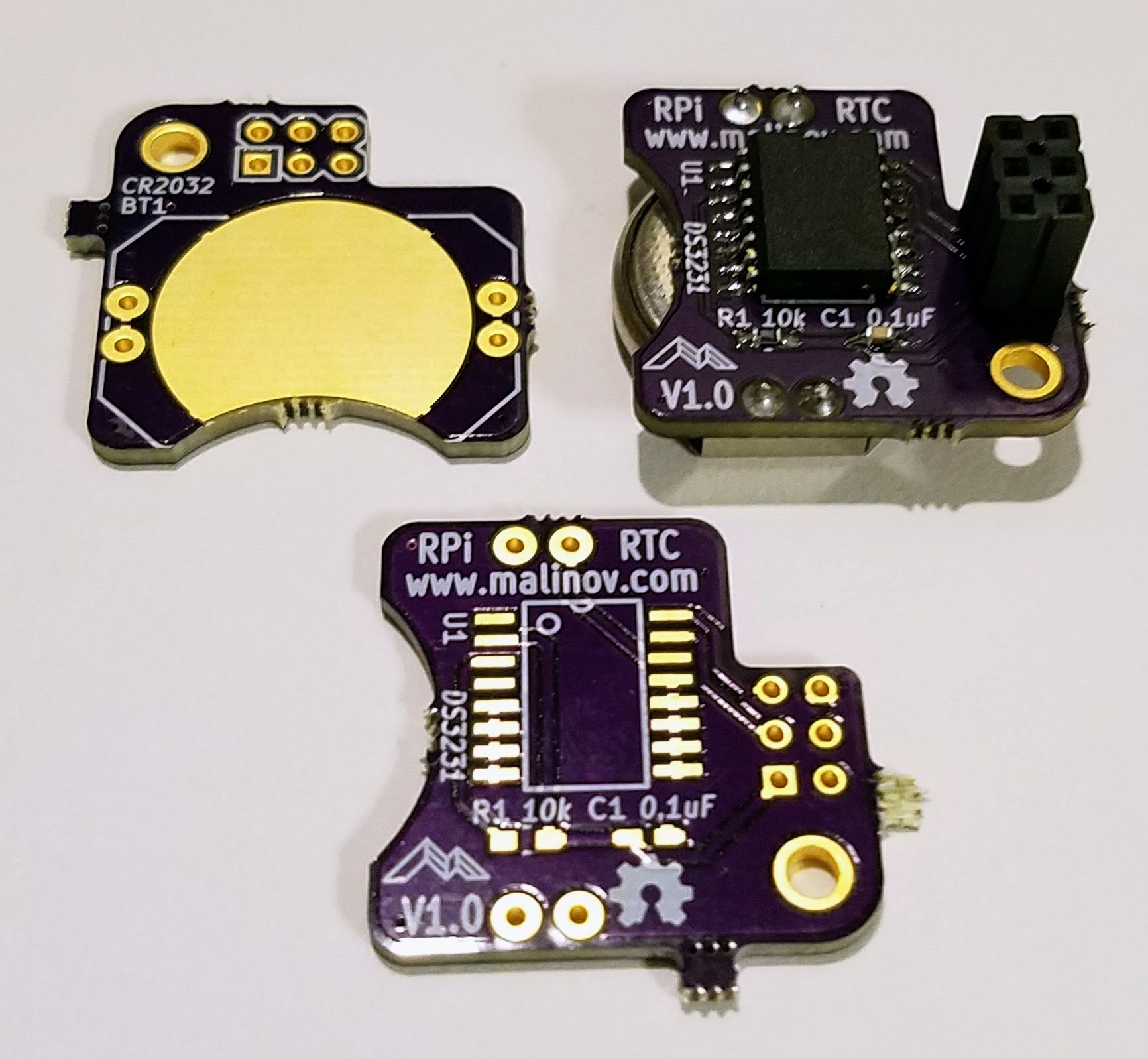
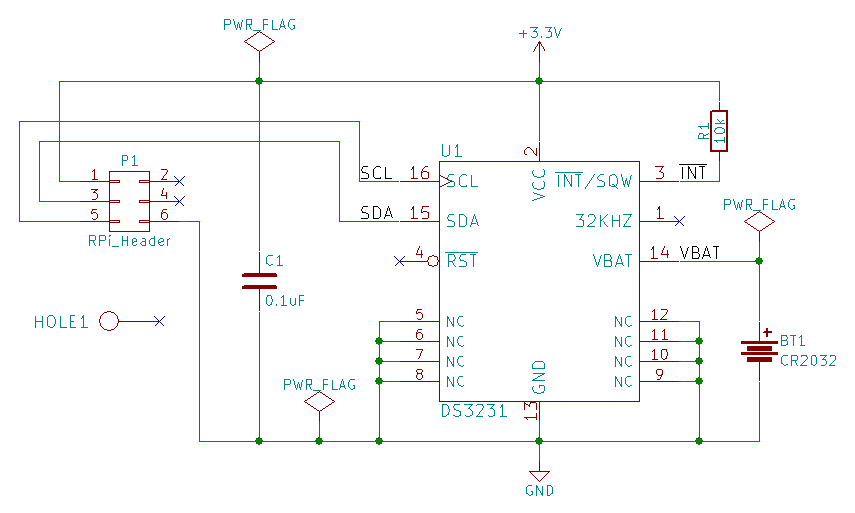
RPi DS3231 RTC project on Mouser.com - View and order all components except of the PCB.
RPi DS3231 RTC on OSH Park - View and order the PCB.
| Component type | Reference | Description | Quantity | Possible sources and notes |
|---|---|---|---|---|
| PCB | RPi DS3231 RTC PCB - Version 1.0 | 1 | Order from OSH Park | |
| Integrated Circuit | U1 | Maxim DS3231 | 1 | Mouser 700-DS3231S#T&R- |
| Capactior | C1 | 0.1uF, 0603 | 6 | Mouser 77-VJ0603Y104JXJPBC |
| Resistor | R1 | 10 kohm, 0603 | 1 | Mouser 71-CRCW060310K0FKEB |
| Connector | P1 | 3x2, 2.54 mm, socket | 1 | Mouser 517-929852-01-03-RA |
| Battery Holder | BT1 | CR2032 Battery Holder | 1 | Mouser 712-BAT-HLD-001-THM |
| Battery | BT1 | CR2032 | 1 | Mouser 658-CR2032 |
The following steps assume that you have a fairly new Rapbian distribution installed and running on your Rapsberry Pi, and that RPi DS3231 RTC module is plugged into the Raspberry Pi.
Run raspi-config:
$ sudo raspi-configNavigate to the Interfacing Options menu. If this menu is missing (on older Raspbian versions), try the Advanced Options menu instead. Next, select the I2C menu, and answer Yes to Would you like the ARM I2C interface to be enabled? and Would you like the I2C kernel modules to be loaded by default? questions.
Reboot the system
Install i2c-tools package:
$ sudo apt-get install i2c-toolsRun i2cdetect -y 1 command and verify that the I2C device is detected at address 0x68:
$ sudo i2cdetect -y 1
     0  1  2  3  4  5  6  7  8  9  a  b  c  d  e  f
00:          -- -- -- -- -- -- -- -- -- -- -- -- --
10: -- -- -- -- -- -- -- -- -- -- -- -- -- -- -- --
20: -- -- -- -- -- -- -- -- -- -- -- -- -- -- -- --
30: -- -- -- -- -- -- -- -- -- -- -- -- -- -- -- --
40: -- -- -- -- -- -- -- -- -- -- -- -- -- -- -- --
50: -- -- -- -- -- -- -- -- -- -- -- -- -- -- -- --
60: -- -- -- -- -- -- -- -- 68 -- -- -- -- -- -- --
70: -- -- -- -- -- -- -- --Open /boot/firmware/config.txt in your favorite editor (nano, vi) as root. For example:
$ sudo nano /boot/firmware/config.txtAdd the following lines at the end of the file:
# Enable DS3231 RTC
dtoverlay=i2c-rtc,ds3231
Remove fake-hwclock package:
$ sudo apt-get -y remove fake-hwclock
$ sudo update-rc.d -f fake-hwclock remove
Enable setting up system time to the RTC time at boot. Open /lib/udev/hwclock-set in your favorite editor:
$ sudo nano /lib/udev/hwclock-setAnd comment out the following lines:
#if [ -e /run/systemd/system ] ; then
# exit 0
#fi
Also comment the following line(s):
#/sbin/hwclock --rtc=$dev --systz --badyear
#/sbin/hwclock --rtc=$dev --systz
Save the file, and reboot the system
hwclock -w command to set the RTC time to the system time. You can use date command to set and verify the system time prior to writing it to the RTC.hwclock --set --date=<date_string> command to set the RTC time to the time given by <date_string>hwclock -r command to read the time from the RTC| Qty | Value | Footprint | References |
|---|---|---|---|
| 1 | 0.1uF | Capacitors_SMD:C_0603_HandSoldering | C1 |
| 1 | 10k | Resistors_SMD:R_0603_HandSoldering | R1 |
| 1 | CR2032 | my_components:Battery_Holder_CR2032_THM | BT1 |
| 1 | DS3231 | my_components:IC_SOIC16_Wide | U1 |
| 1 | HOLE | my_components:Hole_2.75mm | HOLE1 |
| 1 | OSHW-logo_silkscreen-front_4mm | OSHW-logo:OSHW-logo_silkscreen-front_4mm | G*** |
| 1 | RPi_Header | my_components:Conn_Pin_Header_2x3_2.54mm | P1 |


PCBench/PCBench
resolution = [0.5, 0.5] pcbfolder = '../PCBs/' pcbnames = ["1Bitsy1bitsy"] iters = 30 env = PCBRoutingEnv(resolution=resolution, pcbfolder=pcbfolder, pcbnames=pcbnames) obs, info = env.reset() for in range(iters): act =…

dm2lct/tlnixie
PCB files for the Turmlabor nixie clock 2.0

mistic100/Nixie-Clock-IN2
Check out my other projects: - Nixie Clock IN14 - Nixie Clock IN12 - IV-27 VFD Clock
It measures 32.5 × 24 mm and has 2 copper layers, 1.6 mm thick.
7 parts, built around the DS3231S# and CR2032. The full list of its parts is on this page, with links to each part's symbol and footprint where PCBKit's library has them.
From the skiselev/rpi_rtc_ds3231 repository on GitHub, at the commit this page was made from: the board is KiCad/rpi_rtc.kicad_pcb. PCBKit opens the board in the browser, with nothing to install.
Its repository publishes it under the GPL-3.0 licence: you may reuse it on that licence's terms (keep the author's notice, and for a copyleft licence share your changes alike).