2 layers149 × 8 mm
Buttons board
mistic100/Nixie-Clock-IN2
Check out my other projects: - Nixie Clock IN14 - Nixie Clock IN12 - IV-27 VFD Clock
4 parts10

 mistic100/Nixie-Clock-IN210
Check out my other projects: - Nixie Clock IN14 - Nixie Clock IN12 - IV-27 VFD Clock
In-2-nixie is an open-source printed circuit board by mistic100, from the mistic100/Nixie-Clock-IN2 repository on GitHub. It is a 2-layer board of 167 × 52 mm with 34 parts on 88 nets, routed with 316 tracks and 75 vias.
It is built around the BME280, HV5222PJ-G and WS2812B, with the DS3231S# and MPSA42 among its other parts. Its parts include 9 resistors, 6 connectors, 5 diodes, 4 ICs and 2 capacitors. It belongs with the lEDs and displays boards and the ESP32 and RISC-V boards of this library.


Check out my other projects:
This is a Nixie Clock using small IN-2 tubes and a 16x9 LED matrix. It was mostly inspired by this 3D model 80s Alarm Clock by Tom Seddon.

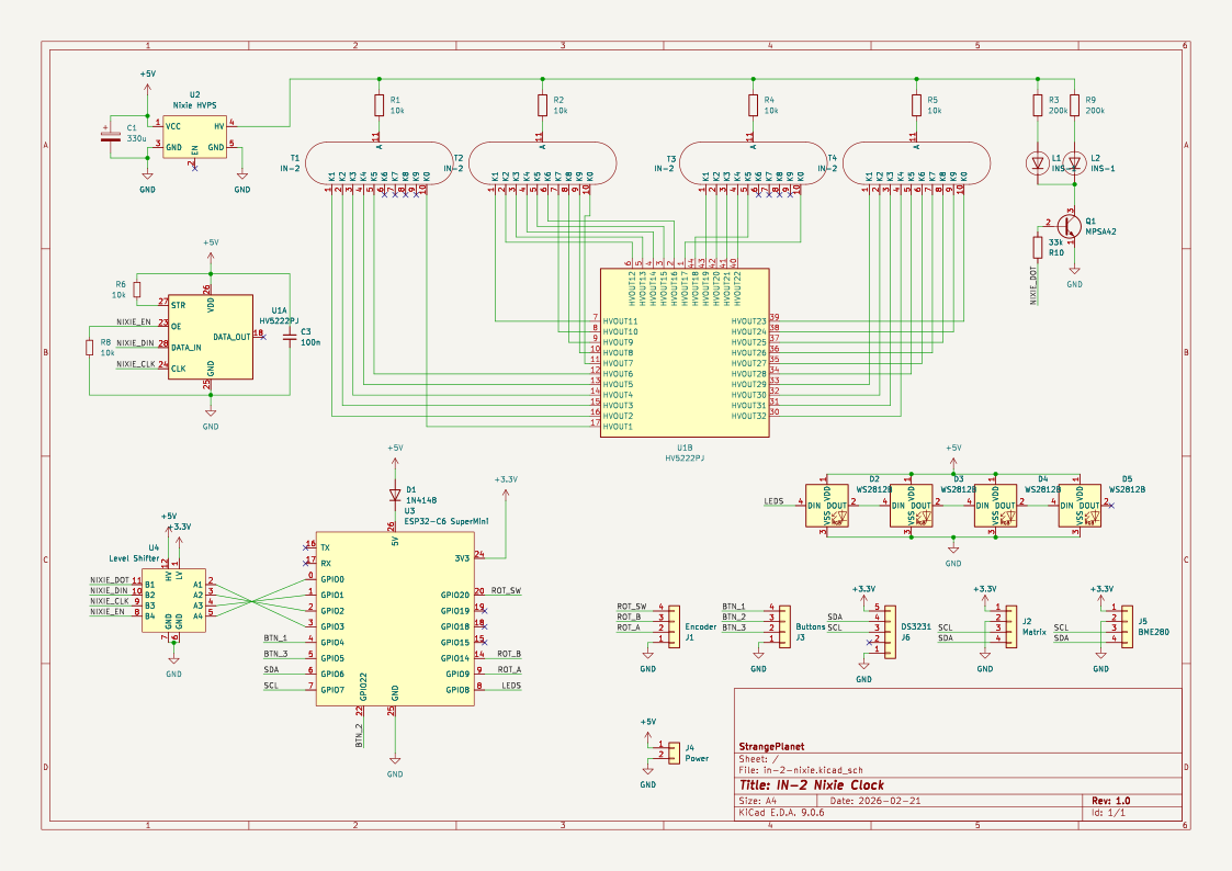
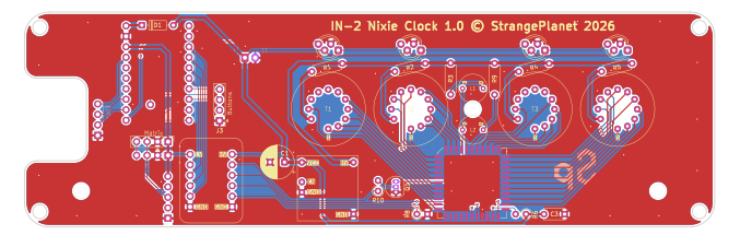
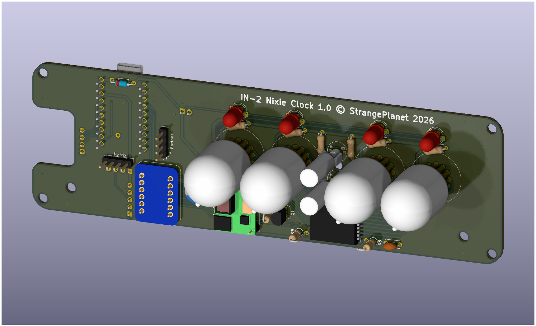
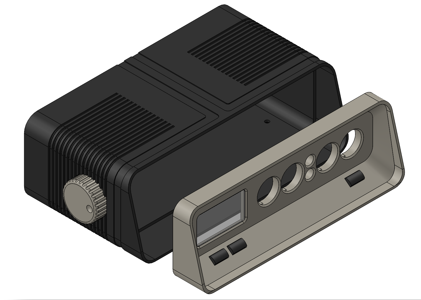
The Arduino code, the KiCad design and SolidWorks files are distributed under the Creative Commons 3.0 BY-SA license.
| Qty | Value | Footprint | References |
|---|---|---|---|
| 4 | 10k | Resistor_THT:R_Axial_DIN0207_L6.3mm_D2.5mm_P7.62mm_Horizontal | R1, R2, R4, R5 |
| 4 | IN-2 | in-2-nixie:IN-2 Nixie Tube (w. pins) | T1, T2, T3, T4 |
| 4 | WS2812B | in-2-nixie:APA106_D5-Staggered_Pins | D2, D3, D4, D5 |
| 2 | 10k | Resistor_THT:R_Axial_DIN0207_L6.3mm_D2.5mm_P2.54mm_Vertical | R6, R8 |
| 2 | 200k | Resistor_THT:R_Axial_DIN0207_L6.3mm_D2.5mm_P7.62mm_Horizontal | R3, R9 |
| 2 | INS-1 | in-2-nixie:INS-1 Nixie Tube | L1, L2 |
| 1 | 100n | Capacitor_THT:C_Disc_D5.0mm_W2.5mm_P5.00mm | C3 |
| 1 | 1N4148 | Diode_THT:D_DO-35_SOD27_P7.62mm_Horizontal | D1 |
| 1 | 330u | Capacitor_THT:CP_Radial_D8.0mm_P3.50mm | C1 |
| 1 | 33k | Resistor_THT:R_Axial_DIN0207_L6.3mm_D2.5mm_P2.54mm_Vertical | R10 |
| 1 | BME280 | Connector_PinHeader_2.54mm:PinHeader_1x04_P2.54mm_Vertical | J5 |
| 1 | Buttons | Connector_PinHeader_2.54mm:PinHeader_1x04_P2.54mm_Vertical | J3 |
| 1 | DS3231 | Connector_PinHeader_2.54mm:PinHeader_1x05_P2.54mm_Vertical | J6 |
| 1 | ESP32-C6 SuperMini | in-2-nixie:ESP32-C6 SuperMini | U3 |
| 1 | Encoder | Connector_PinHeader_2.54mm:PinHeader_1x04_P2.54mm_Vertical | J1 |
| 1 | HV5222PJ | in-2-nixie:PLCC-44 LongPads | U1 |
| 1 | LOGO | in-2-nixie:sp_logo | G*** |
| 1 | Level Shifter | in-2-nixie:Adafruit Level Shifter | U4 |
| 1 | MPSA42 | Package_TO_SOT_THT:TO-92_Inline | Q1 |
| 1 | Matrix | Connector_PinHeader_2.54mm:PinHeader_1x04_P2.54mm_Vertical | J2 |
| 1 | Nixie HVPS | in-2-nixie:Neonwork Nixie Power Supply | U2 |
| 1 | Power | Connector_JST:JST_XH_B2B-XH-A_1x02_P2.50mm_Vertical | J4 |
mistic100/Nixie-Clock-IN2
Check out my other projects: - Nixie Clock IN14 - Nixie Clock IN12 - IV-27 VFD Clock


vascofazza/cloxie_nixie_clock
Schematics and code for Cloxie: my Nixie Tube Clock.


Ezerwald/stm32-kicad-weather-station
KiCad-based PCB project for an STM32-powered IoT weather station with environmental sensing, real-time clock support, battery charging, and e-paper display connectivity.

SimulatedFlow/kicad-board-2026-07-29-bluepill-sensor-node
STM32 Bluepill environmental sensor node carrier - BME280 temperature / humidity / pressure, RTC and OLED display. Solder kit, bare PCB.

dm2lct/tlnixie
PCB files for the Turmlabor nixie clock 2.0
It measures 167 × 52 mm and has 2 copper layers, 1.6 mm thick.
34 parts, built around the BME280, HV5222PJ-G, WS2812B and DS3231S#. The full list of its parts is on this page, with links to each part's symbol and footprint where PCBKit's library has them.
From the mistic100/Nixie-Clock-IN2 repository on GitHub, at the commit this page was made from: the board is main-board/in-2-nixie.kicad_pcb and its schematic buttons-board/buttons-board.kicad_sch. PCBKit opens the board in the browser, with nothing to install.
Its repository states no licence, so its author keeps all rights: ask mistic100 before reusing the design.