
4 layers45 × 76 mm

 PE5PVB/PAL-sign2
Advanced CVBS PAL video generator
PAL sign is an open-source printed circuit board by PE5PVB, from the PE5PVB/PAL-sign repository on GitHub, published under the GPL-3.0 licence. It is a 4-layer board of 100 × 85 mm with 115 parts on 100 nets, routed with 880 tracks and 154 vias.
It is built around the RP2350A, ADV7391BCPZ and THS7314D, with the TPS62160DSG, W25Q128JVSIQ and RV-3028-C7 among its other parts. Its parts include 47 capacitors, 24 resistors, 9 ICs, 7 connectors and 6 diodes. It belongs with the RP2350 boards of this library.


Advanced CVBS PAL test card generator, built around an RP2350 and an ADV7391 video encoder
A standalone hardware test card generator for anyone working with analogue television: an ATV contest, aligning a transmitter or receiver, or just needing a proper PAL B/G composite signal on the bench. Twenty broadcast-standard test cards, generated in real time and sent out as CVBS, no PC required to run it.
Everything below is reachable from the on-device screen and knob, or from the PC tool; the two show the same settings.
A small screen and a rotary encoder on the front, entirely optional: unplug that panel and the firmware skips it and keeps generating video (a pin on the flatcable tells it whether the panel is there). Turning the knob steps through the list of cards without touching what is on air; pushing switches to the highlighted one.
What is offered depends on the card: one with no room for a ticker will not offer one, and one with no clock box will not offer a colour for it. Between them, the twenty cards can offer:
A sequence of steps, each "how long, which card", built by dragging cards into an order in the PC tool. Any card can appear more than once, each occurrence with its own duration, and there is an optional fade between pictures. The sequence is stored in its own flash page and survives a power cycle, so a slideshow left running keeps running after a restart.
A scrolling text band that can run on almost any card, configured per card as listed above: on or off, or transparent over the picture instead of a solid band; where it sits, how fast and in which direction it scrolls; one of five sizes, one of four fonts, and its own colour. The message itself is shared across every card that shows it.
Both cards have their own oval photo window built in; the PC tool's "Upload portrait..." button lets you put your own picture there instead. The two windows are not quite the same size or shape, so one upload feeds both: choose a photo, drag it and use the zoom slider until the right part sits inside both outlines shown on the preview, and both are cut out and sent in one step. Each card keeps its own on/off switch (see the per-card menu above), so you can show your photo on one, the original on the other, or either everywhere.
Six of the twenty, captured straight off the composite output.
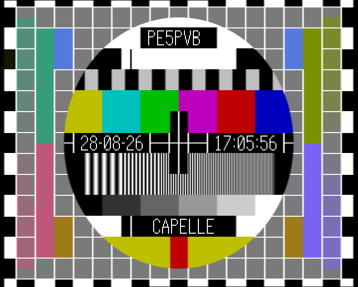 PM5644 The classic Philips PM5644, straight from the original EPROM dump: colour bars, a resolution grating in each corner, a grey scale and the two identification boxes, "PE5PVB" and "CAPELLE" here, with the on-device clock in the middle. | 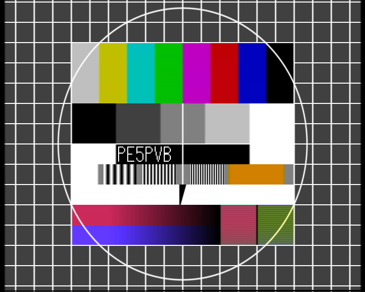 FuBK FuBK, the German counterpart of the PM5544, taken from an actual composite recording. The two striped fields right of the gradient bars deliberately mis-modulate the colour signal; a properly working PAL decoder averages them down to plain grey. | 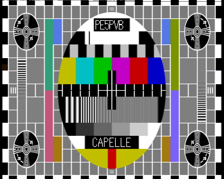 PM5644 16:9 The same PM5644 picture from a newer generation of the encoder EPROM (G924): finer detail and the identification boxes in slightly different places than the plain PM5644. |
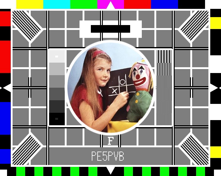 BBC Test Card F The well known girl-and-clown card, rebuilt from the original photo scan, surrounded by colour bars, resolution wedges and a grey scale. | 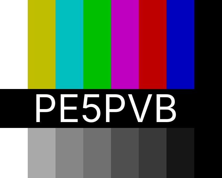 Mixed bars The same eight colour bars twice: once in colour, once with the chroma stripped out, so the bottom row shows exactly the brightness each colour bar carries. | 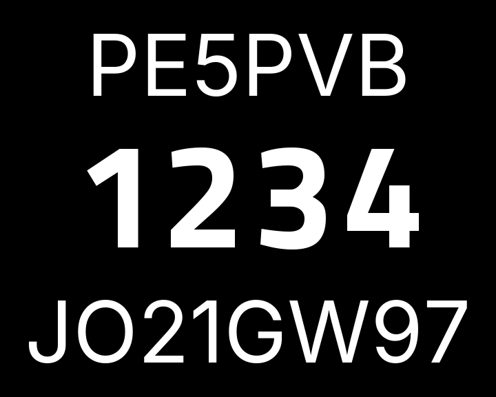 ATV Contest Callsign, contest number and locator in large, legible digits, meant to be read off a weak or noisy signal during a contest. |
The RP2350 does not generate the analogue PAL signal itself. Its PIO hardware (a handful of small, exactly timed state machines built into the chip for jobs like this) pushes the picture out as a digital YCbCr 4:2:2 byte stream on an 8 bit bus, together with a 27 MHz clock, following the BT.656 standard. That digital stream, plus a couple of control pins, goes straight into an Analog Devices ADV7391 video encoder over I2C for configuration. The ADV7391 does the actual PAL encoding: it generates the colour subcarrier, mixes in luma and chroma, adds the analogue sync pulses and drives the composite (CVBS) output.
An older-style video source uses two extra wires next to the picture data, HSYNC and VSYNC, to mark the start of every line and every field. BT.656 does not need them: it puts special byte codes (SAV and EAV, values that never occur in real picture data) straight into the byte stream itself, at the start and end of every active line. The ADV7391 reads its own timing out of those codes, so on this board HSYNC and VSYNC are simply wired high and never toggle.
One RP2350 core works out the pixel data for the current picture, line by line, and writes it into a ring buffer. The other core only reads that buffer back out to the PIO/DMA hardware, at a fixed pace, so the picture can never fall behind: DMA moves the bytes from the buffer into the PIO's FIFO without either core handling them one by one. If the rendering core ever gets too far behind, for instance during a picture switch, the firmware notices and falls back to repeating the last complete picture instead of letting anything incomplete reach the screen.
Teletext, the widescreen signalling (WSS) and the insertion test signal (ITS) are not produced by a separate chip. They are ordinary picture data: a handful of lines in the vertical blanking interval, the lines you never actually see, above and below the visible picture, get filled with luma samples that decode into the teletext bits or the WSS code, exactly like any other line of picture content decodes into a colour. The firmware works out that waveform itself, pulse by pulse, to the shape the relevant standard requires, and writes it straight into the same buffer the ADV7391 streams out.
The twenty built-in test cards are pixel data compiled straight into the firmware; several of them, the PM5644 and BBC cards, come from the original EPROM dumps of real broadcast test card generators. Alongside those sit fourteen Custom slots: plain picture data reserved in the last part of the 16 MB flash chip, which you fill from the PC tool over the same USB serial connection used for firmware uploads.
The screen on the front is a plain SPI display, and the knob next to it is an ordinary quadrature rotary encoder, decoded from a GPIO interrupt so a fast turn is never missed; see "Controls and settings" above for what they do.
The screen and the rotary encoder live on their own small front panel PCB, connected with a flatcable, and the whole panel is optional: one pin on the cable tells the firmware whether it is there, and without it the board runs headless and keeps generating video.
The display is an ST7789P3 SPI panel of 76 x 284 pixels (a window inside the controller's 240 x 320 frame memory), driven over SPI0. The knob is an ordinary quadrature rotary encoder with a push switch; the RP2350's internal pull-ups do the rest, so the panel needs no resistors or capacitors of its own.
| Signal | GPIO | Notes |
|---|---|---|
| Display RST | GP19 | |
| Display CS | GP20 | |
| Display DC | GP21 | low = command |
| Display SCK | GP22 | SPI0 SCK |
| Display MOSI (SDA) | GP23 | SPI0 TX |
| Display backlight | GP26 | active high |
| Panel present | GP24 | tie to GND on the panel |
| Encoder phase A | GP27 | internal pull-up |
| Encoder phase B | GP28 | internal pull-up |
| Encoder push | GP29 | internal pull-up |
Plus 3.3 V and GND for the panel itself. The encoder's common and the switch's other side go to GND.
An optional PCM1808 audio ADC turns the generator into a video-plus-audio source: the analogue stereo input is sampled at 48 kHz and embedded in the picture itself as data lines, in the spirit of the PCM adaptors of the early digital audio era. Two extra cards carry it:
Both cards appear automatically when the ADC is detected at power-on, and stay completely hidden without it, on the board, in the menu and in the PC tool alike. The PcmDecoder tool in PC Software/ plays the audio back on a PC from a composite capture card, with a live view of the decode quality.
The ADC connects over I2S, with the PCM1808 in master mode: the board supplies only the 12.288 MHz system clock, and the ADC generates its own bit and word clocks from it.
| Signal | GPIO | Direction |
|---|---|---|
| SCKI (256 fs master clock) | GP13 | board to ADC |
| BCK (bit clock) | GP9 | ADC to board |
| LRCK (word clock) | GP10 | ADC to board |
| DOUT (I2S data) | GP11 | ADC to board |
Plus supply and GND for the ADC board. The PCM1808's mode pins go high for master mode (MD1 = MD0 = high).
Firmware/ -- the firmware for the RP2350, built with PlatformIO or the Arduino IDEPC Software/ -- the Windows configurator, see its own README for how to build and use itHardware/Kicad/ -- the PCB designcd Firmware
pio run
pio run -t uploadPlatformIO picks up everything it needs from platformio.ini, including the board profile for the bare RP2350. Opening Firmware.ino in the Arduino IDE (2.x) works as well; sketch.yaml carries the same board settings.
Found a bug or have an idea? Open an issue or a pull request, I will review it and merge into main. Since this project is dual-licensed (see below), a pull request means you agree that your contribution is licensed the same way as the rest of the project, under both the GPLv3 and the commercial license.
This project is dual-licensed.
You may use it under the terms of the GNU General Public License, either version 3 of the License, or (at your option) any later version: this program is free software, you can redistribute it and/or modify it under those terms. It is distributed in the hope that it will be useful, but WITHOUT ANY WARRANTY; without even the implied warranty of MERCHANTABILITY or FITNESS FOR A PARTICULAR PURPOSE. See the LICENSE file for the full text.
If the GPLv3's terms do not suit your use, for example because you want to use this project, or a part of it, in a closed-source or commercial product without releasing your own source code, a separate commercial license is available. See pe5pvb.nl for contact details.
| Qty | Value | Footprint | References |
|---|---|---|---|
| 25 | 100n | Capacitor_SMD:C_0603_1608Metric | C10, C12, C13, C14, C15, C16, C17, C18, C19, C20, C21, C22, C25, C28, C32, C34 +9 |
| 5 | 4.7uF | Capacitor_SMD:C_0603_1608Metric | C1, C2, C5, C6, C9 |
| 5 | 5k1 | Resistor_SMD:R_0603_1608Metric | R9, R10, R11, R12, R13 |
| 4 | 10uF | Capacitor_SMD:C_0603_1608Metric | C23, C38, C43, C46 |
| 4 | M3 | MountingHole:MountingHole_3.2mm_M3_Pad | H1, H2, H3, H4 |
| 3 | 10k | Resistor_SMD:R_0603_1608Metric | R1, R16, R18 |
| 3 | 470uF | Capacitor_SMD:CP_Elec_8x10 | C31, C33, C36 |
| 3 | 75 | Resistor_SMD:R_0603_1608Metric | R20, R21, R22 |
| 3 | BLM18PG331SN1D | Inductor_SMD:L_0603_1608Metric | FB2, FB3, FB4 |
| 3 | CG0603MLC-05LE | Diode_SMD:D_0603_1608Metric | D3, D4, D5 |
| 3 | Fiducial | Fiducial:Fiducial_1mm_Mask2mm | FID1, FID2, FID3 |
| 2 | 10n | Capacitor_SMD:C_0603_1608Metric | C24, C27 |
| 2 | 15p | Capacitor_SMD:C_0603_1608Metric | C3, C4 |
| 2 | 1k | Resistor_SMD:R_0603_1608Metric | R3, R4 |
| 2 | 2.2uH | Inductor_SMD:L_1008_2520Metric | L5, L6 |
| 2 | 22uF | Capacitor_SMD:C_0805_2012Metric | C40, C41 |
| 2 | 27.4 | Resistor_SMD:R_0603_1608Metric | R5, R6 |
| 2 | B5819W | Diode_SMD:D_SOD-123 | D1, D6 |
| 2 | BLM18HG601SN1D | Inductor_SMD:L_0603_1608Metric | FB1, FB5 |
| 1 | 1.5uH | Inductor_SMD:L_0805_2012Metric | L4 |
| 1 | 12402012E212A | Library:12402012E212A | J1 |
| 1 | 12n | Capacitor_SMD:C_0603_1608Metric | C30 |
| 1 | 150 | Resistor_SMD:R_0603_1608Metric | R17 |
| 1 | 150n | Capacitor_SMD:C_0603_1608Metric | C29 |
| 1 | 1M | Resistor_SMD:R_0603_1608Metric | R7 |
| 1 | 1M1 | Resistor_SMD:R_0603_1608Metric | R23 |
| 1 | 2.2nF | Capacitor_SMD:C_0603_1608Metric | C26 |
| 1 | 20 | Resistor_SMD:R_0603_1608Metric | R19 |
| 1 | 210k | Resistor_SMD:R_0603_1608Metric | R24 |
| 1 | 2k2 | Resistor_SMD:R_0603_1608Metric | R8 |
| 1 | 3.3uH | Library:L_0806_2016Metric | L1 |
| 1 | 300 | Resistor_SMD:R_0603_1608Metric | R15 |
| 1 | 33 | Resistor_SMD:R_0603_1608Metric | R2 |
| 1 | 4.7uH | Inductor_SMD:L_0805_2012Metric | L3 |
| 1 | 4k12 | Resistor_SMD:R_0603_1608Metric | R14 |
| 1 | 4n7 | Capacitor_SMD:C_0603_1608Metric | C11 |
| 1 | ABM8-272-T3 | Crystal:Crystal_SMD_3225-4Pin_3.2x2.5mm | Y1 |
| 1 | ACM2012-201-2P-T001 | Library:FIL_ACM2012-900-2P-T002 | L2 |
| 1 | ACT | LED_SMD:LED_0603_1608Metric | D2 |
| 1 | ADV7391BCPZ | Package_CSP:LFCSP-32-1EP_5x5mm_P0.5mm_EP3.1x3.1mm | U4 |
| 1 | BOOT | Button_Switch_SMD:SW_SPST_B3U-1000P | SW1 |
| 1 | Barrel_Jack_Switch | Connector_BarrelJack:BarrelJack_GCT_DCJ200-10-A_Horizontal | J7 |
| 1 | FRONT | Connector_PinHeader_2.54mm:PinHeader_2x06_P2.54mm_Vertical | J3 |
| 1 | I2S | Connector_PinHeader_2.54mm:PinHeader_2x04_P2.54mm_Vertical | J2 |
| 1 | LOGO | Library:palsignlogo | G*** |
| 1 | ML2032 | Library:CR2032-BS-6-1 | BT1 |
| 1 | RP2350A | Package_DFN_QFN:QFN-60-1EP_7x7mm_P0.4mm_EP3.4x3.4mm | U3 |
| 1 | RV-3028-C7 | Package_SON:MicroCrystal_C7_SON-8_1.5x3.2mm_P0.9mm | U5 |
| 1 | THS7314 | Package_SO:SOIC-8_3.9x4.9mm_P1.27mm | U6 |
| 1 | TPS62160DSG | Package_SON:Texas_DSG0008A_WSON-8-1EP_2x2mm_P0.5mm_EP0.9x1.6mm_ThermalVias | U7 |
| 1 | TPS7A2018PDBVR | Package_TO_SOT_SMD:SOT-23-5 | U9 |
| 1 | TPS7A2033PDBVR | Package_TO_SOT_SMD:SOT-23-5 | U8 |
| 1 | USBLC6-2P6 | Package_TO_SOT_SMD:SOT-666 | U2 |
| 1 | VIDEO1 | Library:RF1-01A-D-00-75-M | J4 |
| 1 | VIDEO2 | Library:RF1-01A-D-00-75-M | J5 |
| 1 | VIDEO3 | Library:RF1-01A-D-00-75-M | J6 |
| 1 | W25Q128JVS | Package_SO:SOIC-8_5.3x5.3mm_P1.27mm | U1 |

HearnChristian/k-band-fmcw-radar
24 GHz FMCW radar front-end in KiCad (WIP): ADF4159 chirp synth, BGT24LTR11 transceiver, custom Marki AMM-8211PSM driver-amp symbol/footprint, OPA1656 IF, ADS8353 ADC, FT2232H USB.

Ash-tronix/nile_test_chip_pcb
KiCad PCB design files to support the Ashtronix® Nile test chip.

cfbird/usb3-sdr
USB3 direct-sampling HF SDR: AD9649 ADC -> ECP5 FPGA DDC -> FT601 USB 3. KiCad 9 + Verilog, co-designed by Claude and Gemini (AGY).


It measures 100 × 85 mm and has 4 copper layers, 1.6 mm thick.
115 parts, built around the RP2350A, ADV7391BCPZ, THS7314D and TPS62160DSG. The full list of its parts is on this page, with links to each part's symbol and footprint where PCBKit's library has them.
From the PE5PVB/PAL-sign repository on GitHub, at the commit this page was made from: the board is Hardware/Kicad/PAL-sign.kicad_pcb and its schematic Hardware/Kicad/PAL-sign.kicad_sch. PCBKit opens the board in the browser, with nothing to install.
Its repository publishes it under the GPL-3.0 licence: you may reuse it on that licence's terms (keep the author's notice, and for a copyleft licence share your changes alike).