


2 layers99.6 × 99.7 mm
Complete Schematic V5
JoshuaMularczyk/Software_Defined_Radio_Receiver
This project was taken on with the goal to create a Software Defined Radio (SDR) in coolaboration with my partner Christian Williams.
74 parts1MIT

Software Defined Radio for MF bands using STM32F042
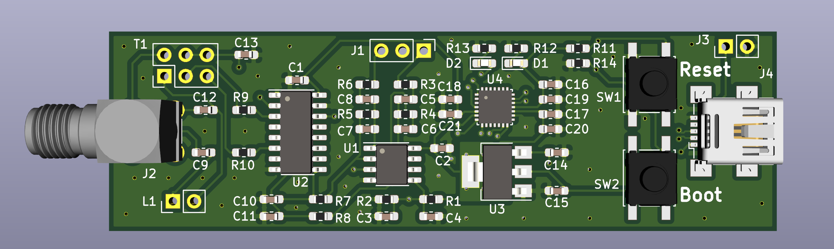
Sdr is an open-source printed circuit board by pd0wm, from the pd0wm/simple-sdr repository on GitHub, published under the MIT licence. It is a 2-layer board of 79.8 × 23.9 mm with 49 parts on 52 nets, routed with 292 tracks and 67 vias.
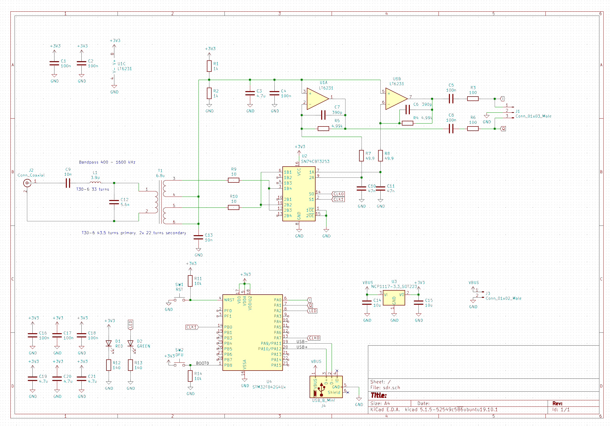
It is built around the LT6231 and SN74CBT3253D. Its parts include 21 capacitors, 14 resistors, 4 ICs, 4 connectors and 2 diodes. It belongs with the radio and wireless boards and the STM32 boards of this library.
Simple Software Defined Radio based on Softrock Lite II. The IF generation and sampling is handled by an STM32F042. This design is intended to build a low cost NAVTEX receiver, but can be used for all kinds of purposes. The current design has an input bandpass filter ranging from 400 - 1600 KHz.
WARNING: So far I haven't been able to receive anything yet with this hardware. Please use at your own risk.
| Qty | Value | Footprint | References |
|---|---|---|---|
| 8 | 100n | Capacitor_SMD:C_0603_1608Metric_Pad1.05x0.95mm_HandSolder | C1, C2, C4, C5, C8, C16, C17, C18 |
| 4 | 4.7u | Capacitor_SMD:C_0603_1608Metric_Pad1.05x0.95mm_HandSolder | C3, C19, C20, C21 |
| 2 | 10 | Resistor_SMD:R_0603_1608Metric_Pad1.05x0.95mm_HandSolder | R9, R10 |
| 2 | 100 | Resistor_SMD:R_0603_1608Metric_Pad1.05x0.95mm_HandSolder | R3, R6 |
| 2 | 10k | Resistor_SMD:R_0603_1608Metric_Pad1.05x0.95mm_HandSolder | R11, R14 |
| 2 | 10n | Capacitor_SMD:C_0603_1608Metric_Pad1.05x0.95mm_HandSolder | C9, C13 |
| 2 | 10u | Capacitor_SMD:C_0603_1608Metric_Pad1.05x0.95mm_HandSolder | C14, C15 |
| 2 | 140 | Resistor_SMD:R_0603_1608Metric_Pad1.05x0.95mm_HandSolder | R12, R13 |
| 2 | 1k | Resistor_SMD:R_0603_1608Metric_Pad1.05x0.95mm_HandSolder | R1, R2 |
| 2 | 390p | Capacitor_SMD:C_0603_1608Metric_Pad1.05x0.95mm_HandSolder | C6, C7 |
| 2 | 4.99k | Resistor_SMD:R_0603_1608Metric_Pad1.05x0.95mm_HandSolder | R4, R5 |
| 2 | 47n | Capacitor_SMD:C_0603_1608Metric_Pad1.05x0.95mm_HandSolder | C10, C11 |
| 2 | 49.9 | Resistor_SMD:R_0603_1608Metric_Pad1.05x0.95mm_HandSolder | R7, R8 |
| 1 | 3.9u | Connector_PinHeader_2.54mm:PinHeader_1x02_P2.54mm_Vertical | L1 |
| 1 | 5.6n | Capacitor_SMD:C_0603_1608Metric_Pad1.05x0.95mm_HandSolder | C12 |
| 1 | 6.8u | Connector_PinHeader_2.54mm:PinHeader_2x03_P2.54mm_Vertical | T1 |
| 1 | Conn_01x02_Male | Connector_PinHeader_2.54mm:PinHeader_1x02_P2.54mm_Vertical | J3 |
| 1 | Conn_01x03_Male | Connector_PinHeader_2.54mm:PinHeader_1x03_P2.54mm_Vertical | J1 |
| 1 | Conn_Coaxial | Connector_Coaxial:SMA_Amphenol_901-144_Vertical | J2 |
| 1 | DFU | Button_Switch_SMD:SW_SPST_EVQQ2 | SW2 |
| 1 | GREEN | LED_SMD:LED_0603_1608Metric_Pad1.05x0.95mm_HandSolder | D2 |
| 1 | LT6231 | Package_SO:SOIC-8_3.9x4.9mm_P1.27mm | U1 |
| 1 | NCP1117-3.3_SOT223 | Package_TO_SOT_SMD:SOT-223-3_TabPin2 | U3 |
| 1 | RED | LED_SMD:LED_0603_1608Metric_Pad1.05x0.95mm_HandSolder | D1 |
| 1 | RST | Button_Switch_SMD:SW_SPST_EVQQ2 | SW1 |
| 1 | SN74CBT3253 | Package_SO:SOIC-16_3.9x9.9mm_P1.27mm | U2 |
| 1 | STM32F042G4Ux | Package_DFN_QFN:QFN-28_4x4mm_P0.5mm | U4 |
| 1 | USB_B_Mini | Connector_USB:USB_Mini-B_Wuerth_65100516121_Horizontal | J4 |
It measures 79.8 × 23.9 mm and has 2 copper layers, 1.6 mm thick.
49 parts, built around the LT6231 and SN74CBT3253D. The full list of its parts is on this page, with links to each part's symbol and footprint where PCBKit's library has them.
From the pd0wm/simple-sdr repository on GitHub, at the commit this page was made from: the board is pcb/sdr.kicad_pcb. PCBKit opens the board in the browser, with nothing to install.
Its repository publishes it under the MIT licence: you may reuse it on that licence's terms (keep the author's notice, and for a copyleft licence share your changes alike).
JoshuaMularczyk/Software_Defined_Radio_Receiver
This project was taken on with the goal to create a Software Defined Radio (SDR) in coolaboration with my partner Christian Williams.

greenjacketgirl/SDR_Receiver
This project is an attempt at designing and building a Software Defined Radio receiver that has the capabilities of listening to frequencies ranging from 500kHz to 50MHz utlizing the board designed, a sound card, and…


SimoneDamian/RP_Spectroscopy_kicad
Circuits for the hardware part of the project


LadyRoninEngineer/Si473x
Data Supporting development of Si473x series radios

Dizzerin/Software-Defined-Radio
Quadrature sampling down converter software defined radio

cernohorsky/DeltaSDR
HF Software Defined Radio Transceiver that includes ADC and DAC circuits. No soundcard is needed. Board communicates only trough one USB cable.