4 layers110 × 175 mm
Printer Mainboard
NEOgHacking/SCORPION-MAX-V1
4x Power Mosfets for controlling heated beds, heaters, ext.
286 parts3

 pcb-firmware-embedded/Atmega16A_temperature_monitoring
This repository contains the complete development of a temperature monitoring and alarm system based on the ATmega16A microcontroller.
05 Atmega16 IoT is an open-source printed circuit board by pcb-firmware-embedded, from the pcb-firmware-embedded/Atmega16A_temperature_monitoring repository on GitHub. It is a 2-layer board of 74 × 56 mm with 29 parts on 65 nets, routed with 242 tracks and 22 vias.
It is built around the ATMEGA16A-AU, DHT11 and SPX3819M5-L-3-3, with the G2RL-1A-E DC5 among its other parts. Its parts include 7 capacitors, 5 resistors, 4 ICs, 3 connectors and 2 switches. It belongs with the home automation and IoT boards and the AVR (ATmega, ATtiny) boards of this library.


This repository contains the complete development of a temperature monitoring and alarm system based on the ATmega16A microcontroller.
The project includes:
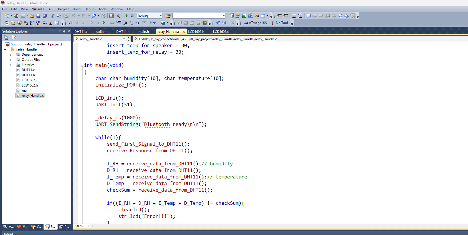
The firmware was written in Embedded C using Atmel Studio.
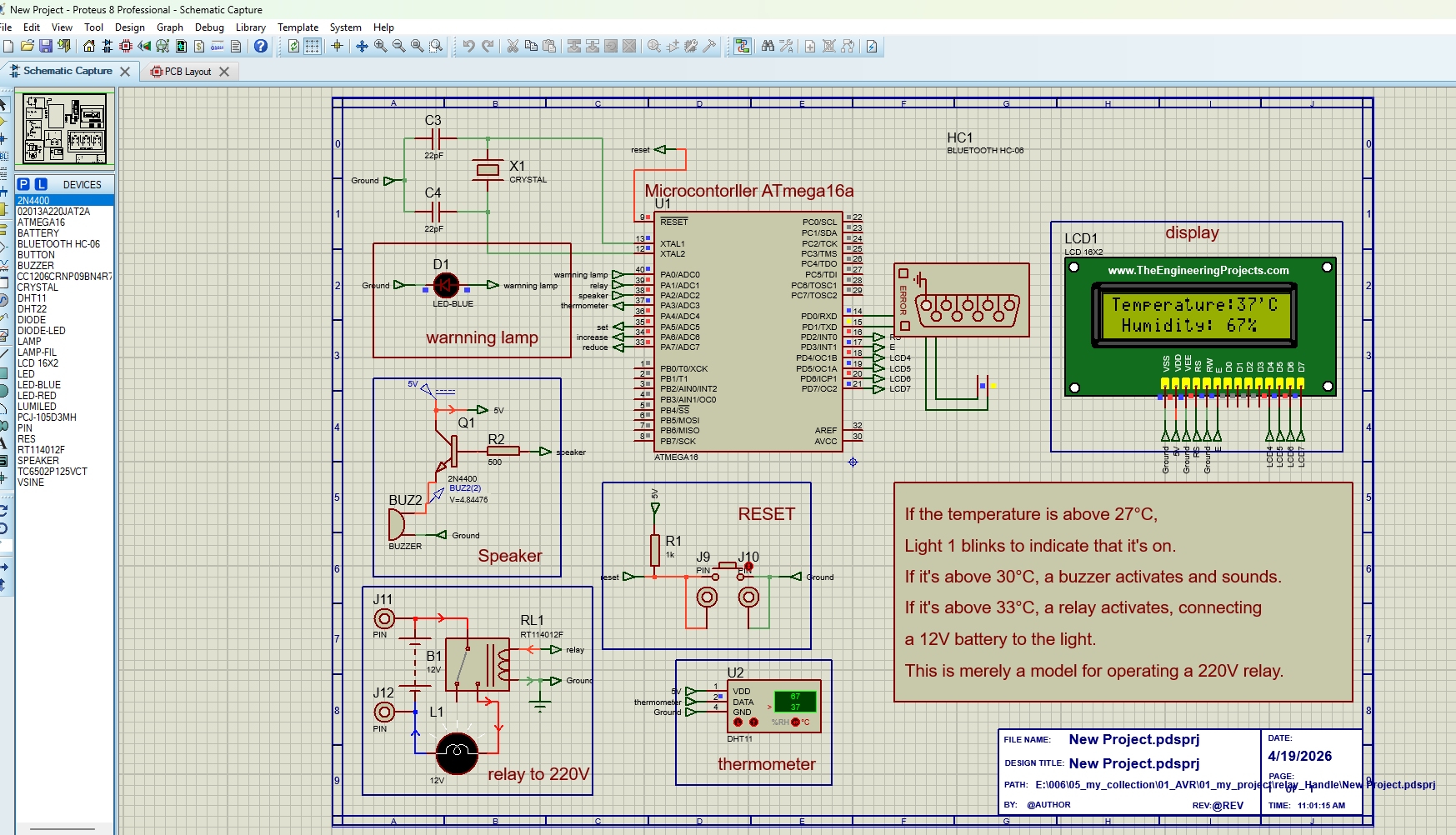
The complete system was verified in Proteus before manufacturing the PCB.
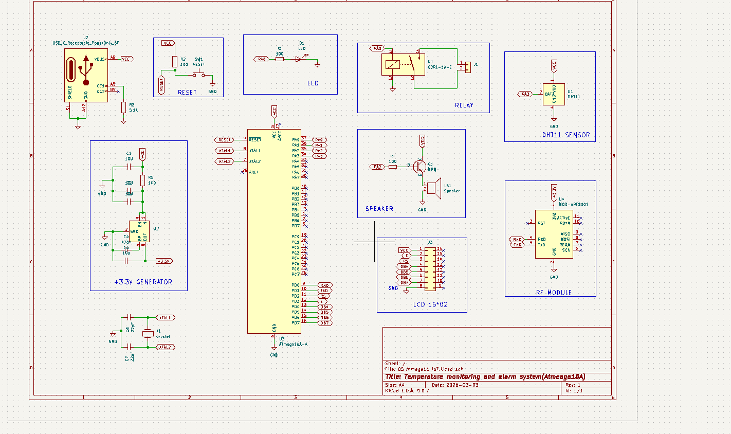
The schematic integrates:
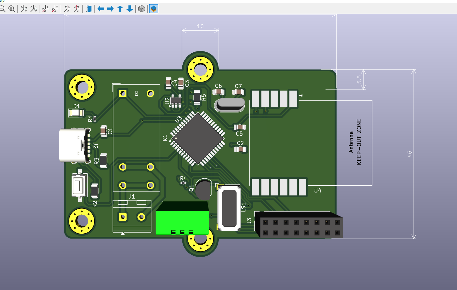
The PCB was designed in KiCad with attention to routing, grounding and component placement.
Firmware Development
        ↓
Proteus Simulation
        ↓
KiCad Schematic
        ↓
PCB Layout
        ↓
Hardware Manufacturing
        ↓
Testing| Qty | Value | Footprint | References |
|---|---|---|---|
| 3 | 10U | Capacitor_SMD:C_0805_2012Metric_Pad1.18x1.45mm_HandSolder | C1, C2, C3 |
| 2 | 100 | Resistor_SMD:R_0402_1005Metric | R1, R4 |
| 2 | 100 | Resistor_SMD:R_1206_3216Metric | R2, R5 |
| 2 | 22pF | Capacitor_SMD:C_0805_2012Metric_Pad1.18x1.45mm_HandSolder | C6, C7 |
| 1 | 10u | Capacitor_SMD:C_0805_2012Metric_Pad1.18x1.45mm_HandSolder | C5 |
| 1 | 470n | Capacitor_SMD:C_0805_2012Metric_Pad1.18x1.45mm_HandSolder | C4 |
| 1 | 5.1k | Resistor_SMD:R_1206_3216Metric | R3 |
| 1 | ATmega16A-A | Package_QFP:TQFP-44_10x10mm_P0.8mm | U3 |
| 1 | Conn_01x02 | TerminalBlock_RND:TerminalBlock_RND_205-00232_1x02_P5.08mm_Horizontal | J1 |
| 1 | Conn_02x08_Counter_Clockwise | Connector_PinSocket_2.54mm:PinSocket_2x08_P2.54mm_Vertical | J3 |
| 1 | Crystal | Crystal:Crystal_HC52-6mm_Vertical | Y1 |
| 1 | DHT11 | Sensor:Aosong_DHT11_5.5x12.0_P2.54mm | U1 |
| 1 | G2RL-1A-E | Relay_THT:Relay_SPST_Omron_G2RL-1A-E | K1 |
| 1 | LED | LED_SMD:LED_1206_3216Metric | D1 |
| 1 | MOD-nRF8001 | RF_Module:MOD-nRF8001 | U4 |
| 1 | NPN | Package_TO_SOT_THT:TO-92 | Q1 |
| 1 | RESET | Button_Switch_SMD:SW_Tactile_SPST_NO_Straight_CK_PTS636Sx25SMTRLFS | SW1 |
| 1 | SPX3819M5-L-3-3 | Package_TO_SOT_SMD:SOT-23-5 | U2 |
| 1 | Speaker | Buzzer_Beeper:Speaker_CUI_CMR-1206S-67 | LS1 |
| 1 | USB_C_Receptacle_PowerOnly_6P | Connector_USB:USB_C_Receptacle_GCT_USB4125-xx-x_6P_TopMnt_Horizontal | J2 |
The 25 most common of 29 parts.
NEOgHacking/SCORPION-MAX-V1
4x Power Mosfets for controlling heated beds, heaters, ext.


kiu/kha
Overengineered Modular RS-485 Multi-Master 19" Subrack Home Automation / Control


vedantjadhav304/Atmega32_DEV_BOARD
Open source AVR embedded system development board based on Atmega32


It measures 74 × 56 mm and has 2 copper layers, 1.6 mm thick.
29 parts, built around the ATMEGA16A-AU, DHT11, SPX3819M5-L-3-3 and G2RL-1A-E DC5. The full list of its parts is on this page, with links to each part's symbol and footprint where PCBKit's library has them.
From the pcb-firmware-embedded/Atmega16A_temperature_monitoring repository on GitHub, at the commit this page was made from: the board is 05_Atmega16_IoT/05_Atmega16_IoT.kicad_pcb and its schematic 05_Atmega16_IoT/05_Atmega16_IoT.kicad_sch. PCBKit opens the board in the browser, with nothing to install.
Its repository states no licence, so its author keeps all rights: ask pcb-firmware-embedded before reusing the design.