

2 layers81.8 × 72.1 mm
SwarmB3 pcb
paulodowd/SwarmB3
Working on Swarm Board version 3... so I decided the tinkering hadn't finished yet :)
54 parts1GPL-3.0

 paulodowd/Swarm-B28
IR Communication board for Pololu 3Pi+ robots that also accommodates an M5 Stack Core2
Swarm B 20230626 is an open-source printed circuit board by paulodowd, from the paulodowd/Swarm-B2 repository on GitHub, published under the GPL-3.0 licence. It is a 2-layer board of 81.8 × 72.1 mm with 32 parts on 62 nets, routed with 336 tracks and 18 vias.
It is built around the TSDP34138 and 74LS32SC. Its parts include 9 connectors, 8 diodes, 7 resistors and 5 ICs. It belongs with the AVR (ATmega, ATtiny) boards of this library.


Infra-red (IR) Communication board for Pololu 3Pi+ robots that also has a pin header to interface with an M5 Stack Core2. This is the second major design of such a board, hence the name (S)warm (B)oard 2 - SwarmB2. A third version is under-development with the intention to supercede this design (SwarmB3).
The board functions as an i2c device, so it should be relatively easy to integrate into other projects using 5v, ground, SCK and SDA connections. The board can communicate with other SwarmB2 boards up to about 2.5m max, or down to less than a centimetre. The firmware for the board has been written with the intention that all (or most) configuration parameters can be set at runtime, so reprogramming firmware shouldn't be necessary.
The best way to get started is to download and install the example M5Visualiser written for the M5Stack Core2. This example demonstrates how to make function calls through the SwarmB2_c class. The class has function calls for all functionality available on the Swarm-B2, returning data types specified in the file ircomm_i2c.h.
To get started with the M5Stack Core2, it is best to follow the manufacturers documentation to configure the Arduino IDE. Make sure you follow the instructions for both:
The M5Visualiser example was written against the M5Unified library - installing or using a different M5Stack library is likely to cause compilation errors for the provided example.
The Swarm-B2 can receive a message of maximum length 32 bytes to transmit. This limitation is currently defined by the Arduino i2c implementation. The Swarm-B2 can accept a message of upto 32bytes, and it will then encode the message using a further number of bytes. It is important to consider that when transmitting a long length message, the probability that the message will become corrupted (or similar) increases.

The Swarm-B2 must disable receiving to be able to transmit, otherwise it will immediately receive it's own transmission. Therefore, the board is configured to periodically transmit messages, and in the interval period poll the receivers to receive messages.
The power of the IR LEDs which transmit messages can be varied via the blue potentiometer on the back of the Swarm-B2 circuit board. The blue potentiometer has a small silver dot: rotating the white arrow indicator to point at this silver dot will produce maximum power, or maximum range of transmission. Swarm-B2 can transmit upto 3m distance. However, this is not very useful in a swarm/multi-robot context. If the transmit power is set high, it is likely that the environment will become saturated with IR emissions, effectively blocking transmissions between all other robots. The recommended position for the potentiometer is indicated in the below image with a pink dot. This position sets the communication distance to approximately 20cm, or two robot-body lengths.

It is possible to change the Swarm-B2 configuration via i2c transactions. For example, it is possible to setup a Swarm-B2 to only transmit continously. Or, it is possible to setup the Swarm-B2 to only receive on 1 receiver continuously.
This IR communication board can be used as a general purpose communication board. The firmware on this github page is written as an i2c slave device with address 0x11. It should be possible to use the IR Communication board in it's current design and format with any other device that can operate the I2C protocol. To do so, you simply need to connect the 5v, GND, SCL and SDA pins appropriately to your operating device. These physical pins are labelled on the underside of the circuit board as +RED (5v), -BLK (GND), SDA and SCL, or as 5V, GND, SCL, SDA on the topside of the circuit board.
Navigate to folder pcb to find the last known gerber files sent for manufacturing, Gerbers.zip.
The schematic of the communication board is available in picture format in the images folder and within the pcb folder as KiCad files.
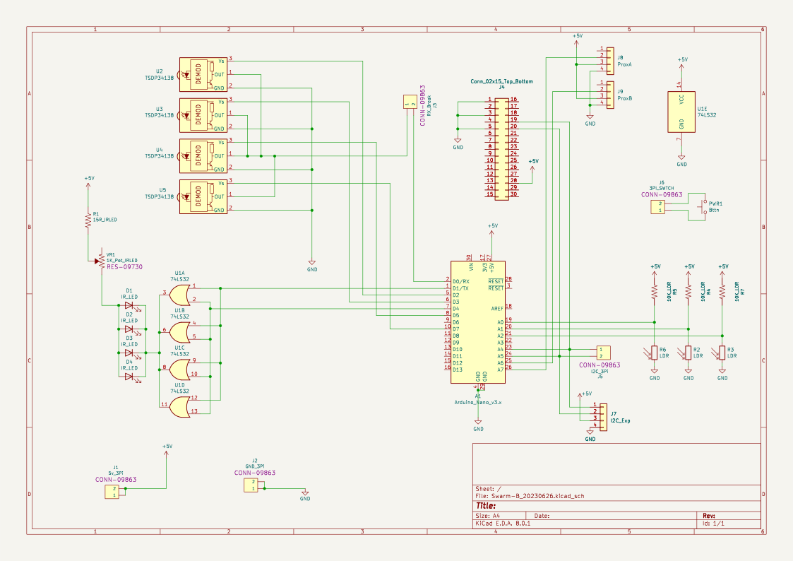
IR communication is implemented using the standard Serial (hardware UART) functionality common to Arduino (e.g. Serial.print()), and so the IR circuit is electronically connected to the Arduino TX and RX pins. The detection (receiving) circuit uses a Demodulator chip that is tuned for a carrier frequency of 38.4Khz or 57.6Khz (more details below). Therefore, the Arduino Nano generates a 38Khz or 58Khz signal via an internal timer interrupt to provide the transmitting carrier, output on digital pin 4.
The carrier signal is combined electronically with the TX pin state through an OR gate (74xx32). The logic (OR) of this operation is defined by the gates sinking the current through the tranmitting IR LEDs. Therefore, the LEDs are not driven by the 74xx32 (or the Arduino Nano, to be clear), and are considered active low. A nice unintended side effect of this is that when TX is inactive (LOW, not transmitting), the 74xx32 output is HIGH despite the continued 38Khz signal generation - which means the IR LEDs are off and not saturating the environment.
In this circuit design, a single gate is used to sink current. It might be important to note that the datasheet for the logic gates specifies a max current sink of 50ma through ground - and here we are potentially sinking upto 200ma from the 4 IR LEDs. So far, I've not seen any significant changes to performance and this may be because I am not sinking current continuously, instead intermitently at 38Khz. All 4 OR gates within the 74xx32 are ganged, but the internal ground connection may still be a limitation. In either case, I haven't yet seen any problems or difference in performance. It might be unwise to active the IR LEDs continuously (i.e. not modulated).
| Qty | Value | Footprint | References |
|---|---|---|---|
| 8 | IR_LED | LED_THT:LED_D3.0mm_Horizontal_O1.27mm_Z2.0mm | D1, D2, D3, D4, D5, D6, D7, D8 |
| 4 | TSDP34138 | OptoDevice:Vishay_MOLD-3Pin | U2, U3, U4, U5 |
| 3 | 10K_LDR | Resistor_THT:R_Axial_DIN0204_L3.6mm_D1.6mm_P7.62mm_Horizontal | R4, R5, R7 |
| 3 | LDR | OptoDevice:R_LDR_5.0x4.1mm_P3mm_Vertical | R2, R3, R6 |
| 1 | 15R_IRLED | Resistor_THT:R_Axial_DIN0204_L3.6mm_D1.6mm_P7.62mm_Horizontal | R1 |
| 1 | 1K_Pot_IRLED | Potentiometer_THT:Potentiometer_Bourns_3386P_Vertical | VR1 |
| 1 | 3PI_SWTCH | Connector_PinHeader_2.54mm:PinHeader_1x02_P2.54mm_Vertical | J6 |
| 1 | 5v_3Pi | Connector_PinHeader_2.54mm:PinHeader_1x02_P2.54mm_Vertical | J1 |
| 1 | 74LS32 | Package_DIP:DIP-14_W7.62mm_Socket | U1 |
| 1 | Arduino_Nano_v3.x | Module:Arduino_Nano | A1 |
| 1 | Bttn | Button_Switch_THT:SW_PUSH_6mm | PWR1 |
| 1 | Conn_02x15_Top_Bottom | Connector_PinHeader_2.54mm:PinHeader_2x15_P2.54mm_Vertical | J4 |
| 1 | GND_3Pi | Connector_PinHeader_2.54mm:PinHeader_1x02_P2.54mm_Vertical | J2 |
| 1 | I2C_3Pi | Connector_PinHeader_2.54mm:PinHeader_1x02_P2.54mm_Vertical | J5 |
| 1 | I2C_Exp | Connector_PinHeader_2.54mm:PinHeader_1x04_P2.54mm_Vertical | J7 |
| 1 | ProxA | Connector_PinHeader_2.54mm:PinHeader_1x04_P2.54mm_Vertical | J8 |
| 1 | ProxB | Connector_PinHeader_2.54mm:PinHeader_1x04_P2.54mm_Vertical | J9 |
| 1 | RX_Break | Connector_PinHeader_2.54mm:PinHeader_1x02_P2.54mm_Vertical | J3 |
paulodowd/SwarmB3
Working on Swarm Board version 3... so I decided the tinkering hadn't finished yet :)


jes/scamp-cpu
A homebrew 16-bit CPU with a homebrew Unix-like-ish operating system.

mudmin/AnotherMaker
This is where I will store code snippets for AnotherMaker Videos


The-Invent0r/8-bit-Computer-PCB
These are the KiCAD files for my 8-Bit Computer.
It measures 81.8 × 72.1 mm and has 2 copper layers, 1.6 mm thick.
32 parts, built around the TSDP34138 and 74LS32SC. The full list of its parts is on this page, with links to each part's symbol and footprint where PCBKit's library has them.
From the paulodowd/Swarm-B2 repository on GitHub, at the commit this page was made from: the board is pcb/Swarm-B_20230626.kicad_pcb and its schematic pcb/Swarm-B_20230626.kicad_sch. PCBKit opens the board in the browser, with nothing to install.
Its repository publishes it under the GPL-3.0 licence: you may reuse it on that licence's terms (keep the author's notice, and for a copyleft licence share your changes alike).