
2 layers139.7 × 73.7 mm
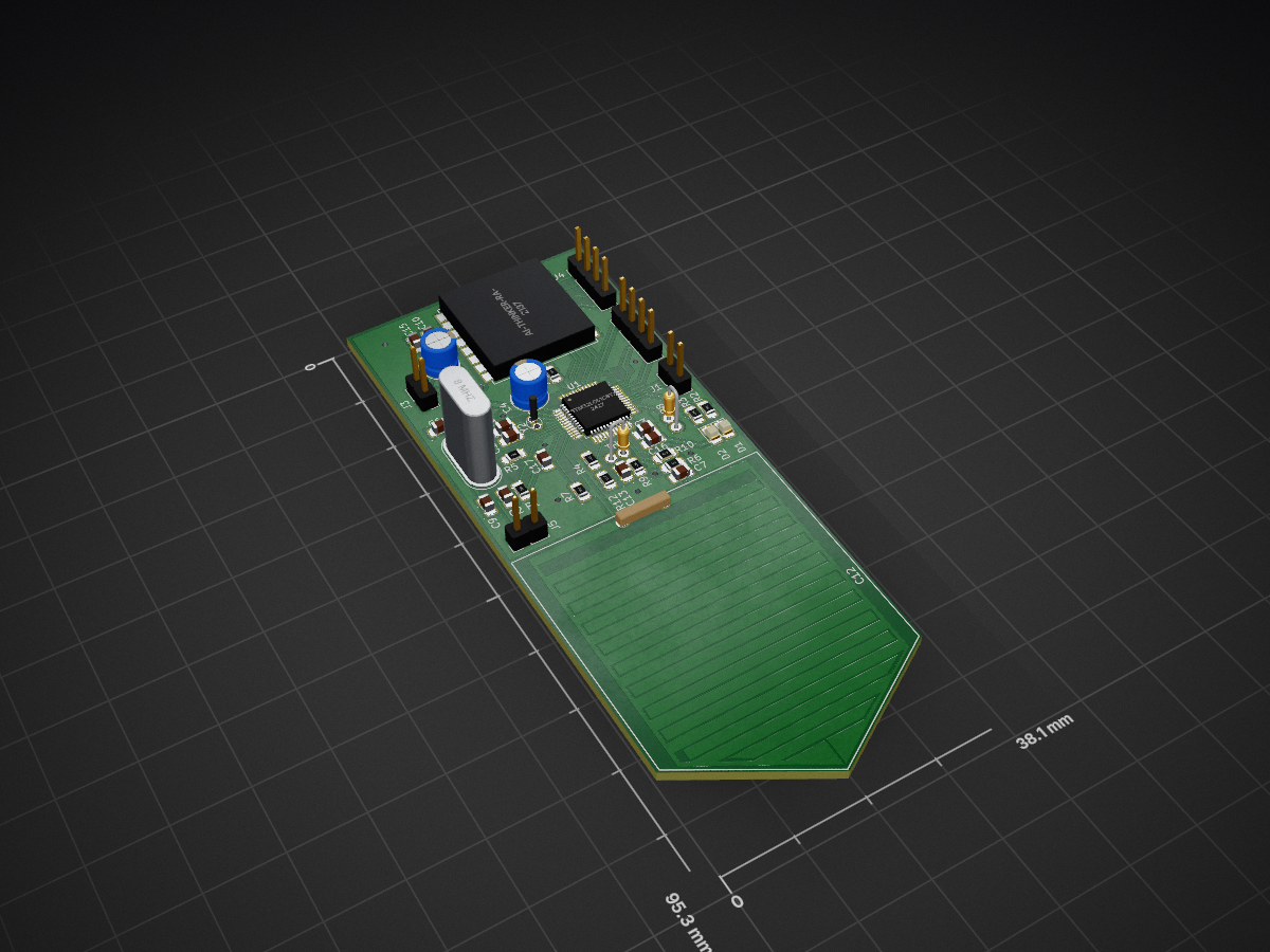
Projet that aims to develop LoRa-connected device capable of measuring temperature, soil moisture and air humidity.
Placa is an open-source printed circuit board by patricktlo, from the patricktlo/IotSoilSensor repository on GitHub. It is a 2-layer board of 38.1 × 95.3 mm with 40 parts on 31 nets, routed with 303 tracks and 11 vias.
Its parts include 16 capacitors, 12 resistors, 5 connectors, 2 ICs and 2 diodes. It belongs with the radio and wireless boards and the STM32 boards of this library.
This project aims to create a cheap LoRa-connected device to measure soil moisture using an embedded capacitive sensor. It also has a temperature sensor (NTC) and an air humidity sensor (HR202).
This project also contains a small simple gateway for LoRa using a LoRa module, a microcontroller and a Raspberry Pi.
For the geometry of the sensor I chose a fringing field capacitive sensor because it is well documented and used in academic papers, it was also easy to design it in KiCAD, and easy to simulate in FEMM.
To measure the capacitance a simple RC circuit is used, where R is chosen to achieve a good resolution and measuring range. A comparator (which is inside the STM32L051 microcontroller) is connected to the output of the RC circuit, a simple resistive divider giving Vcc/2 is connected to the other pin of the comparator.
A square wave is applied to the RC circuit, once the comparator changes state, the code of the MCU gets the value of the timer (the same one used for the square wave generations), with this value it is possible to measure the RC constant and hence the capacitive value. This circuit works quite well, before testing the capacitive sensor with it I tried it with capacitors and the results were really close to the nominal capacitive values (data here)
The gravimetric analysis was used to calibrate our sensor, data can be found here.
The temperature sensor is an NTC thermistor because it's simple, cheap and doesn't depend on battery voltage (like DHT11 and others). The circuit is a simple resistor divider, where the value of the other resistor was chosen by finding the inflection point (using a double derivative, more information on the [HR202 sensor python notebook](1_Simulations/HR202/RH Simulation.ipynb), where I developed the math), you can find the math and some cool graphs on the NTC sensor python notebook.
I used the beta-equation for the NTC, look here for more info.
The value of beta was given in the datasheet but I wanted to get a closer value so I calibrated it, see more details in this spreadsheet.
The air humidity sensor was a tough one, it would've been pretty simple and straightforward to use a DHT11, but it would stop working when battery levels got to 3V (so pretty soon considering I'm using two AA batteries). So, I chose the HR202, there's not much about it but it's basically a resistive sensor, the RH value changes with temperature and you have to apply AC to it.
In order to provide AC voltage, I polarized the output at Vcc/2, using a resistor divider (look into the LTSpice file or the KiCAD schematic for more. The value of the resistor in this resistor divider is crucial because its value (or more precisely, the equivalent value of the two) define the output characteristics. To find the value of the resistors the inflex point was used (more info on the HR202 sensor python notebook).
Also, just a quick note, since the input voltage is a square wave controlled by a timer, and we want to gather data from the ADC in sync with the square wave, it is needed to fire the ADC conversion with a timer as well.
It is difficult to calibrate this sensor, I found that the values in the datasheet weren't close to my results (although it could be some error in the circuit, I later found in another datasheet a somewhat different circuit which could work better). In order to get a fixed relative air humidity, I put the sensor inside a sealed container with a bottle cap of salt and water, that way after a few hours it gets to 75%. I had an air humidity sensor so I could also use it as a reference. Even though the HR202 wasn't giving out exactly what was written on the datasheet, one could see the output voltage had a correlation with the humidity, so I got two known points, the 75% from the salt-water solution and the ambient RH from the other sensor, and fitted my sensor values to this line. It's far from perfect but it does give an idea of the RH.
| Qty | Value | Footprint | References |
|---|---|---|---|
| 5 | 100n | Capacitor_SMD:C_0805_2012Metric_Pad1.15x1.40mm_HandSolder | C2, C3, C8, C15, C17 |
| 4 | 10k | Resistor_SMD:R_0805_2012Metric_Pad1.15x1.40mm_HandSolder | R1, R7, R9, R11 |
| 2 | 10n | Capacitor_SMD:C_0805_2012Metric_Pad1.15x1.40mm_HandSolder | C7, C13 |
| 2 | 10p | Capacitor_SMD:C_0805_2012Metric_Pad1.15x1.40mm_HandSolder | C11, C14 |
| 2 | 20p | Capacitor_SMD:C_0805_2012Metric_Pad1.15x1.40mm_HandSolder | C6, C9 |
| 2 | 22k | Resistor_SMD:R_0805_2012Metric_Pad1.15x1.40mm_HandSolder | R4, R12 |
| 2 | 330 | Resistor_SMD:R_0805_2012Metric_Pad1.15x1.40mm_HandSolder | R2, R3 |
| 2 | 47k | Resistor_SMD:R_0805_2012Metric_Pad1.15x1.40mm_HandSolder | R6, R10 |
| 2 | LED | LED_SMD:LED_0805_2012Metric_Pad1.15x1.40mm_HandSolder | D1, D2 |
| 2 | Screw_Terminal_01x02 | Connector_PinHeader_2.54mm:PinHeader_1x02_P2.54mm_Vertical | J1, J3 |
| 1 | 10u | Capacitor_THT:CP_Radial_D5.0mm_P2.50mm | C4 |
| 1 | 1u | Capacitor_THT:CP_Radial_D5.0mm_P2.00mm | C5 |
| 1 | 32.768 kHz | Crystal:Crystal_Round_D1.0mm_Vertical | Y2 |
| 1 | 390 | Resistor_SMD:R_0805_2012Metric_Pad1.15x1.40mm_HandSolder | R5 |
| 1 | 470n | Capacitor_SMD:C_0805_2012Metric_Pad1.15x1.40mm_HandSolder | C16 |
| 1 | 660n | Capacitor_SMD:C_0805_2012Metric_Pad1.15x1.40mm_HandSolder | C10 |
| 1 | 8 MHz | Crystal:Crystal_HC49-U_Vertical | Y1 |
| 1 | Ai-Thinker-Ra-01 | TCC:Ai-Thinker-Ra-01-LoRa | U2 |
| 1 | C_Variable | TCC:Moisture Sensor | C12 |
| 1 | Conn_01x02_Male | Connector_PinHeader_2.54mm:PinHeader_1x02_P2.54mm_Vertical | J5 |
| 1 | Conn_01x04_Male | Connector_PinHeader_2.54mm:PinHeader_1x04_P2.54mm_Vertical | J2 |
| 1 | HR202 | Resistor_THT:R_Axial_DIN0204_L3.6mm_D1.6mm_P1.90mm_Vertical | R8 |
| 1 | STM32L051C8Tx | Package_QFP:LQFP-48_7x7mm_P0.5mm | U1 |
| 1 | TestPoints | Connector_PinHeader_2.54mm:PinHeader_1x04_P2.54mm_Vertical | J4 |
| 1 | Thermistor | Resistor_THT:R_Axial_DIN0204_L3.6mm_D1.6mm_P1.90mm_Vertical | TH1 |
It measures 38.1 × 95.3 mm and has 2 copper layers, 1.6 mm thick.
40 parts. The full list of its parts is on this page, with links to each part's symbol and footprint where PCBKit's library has them.
From the patricktlo/IotSoilSensor repository on GitHub, at the commit this page was made from: the board is 2_PCB/placa.kicad_pcb. PCBKit opens the board in the browser, with nothing to install.
Its repository states no licence, so its author keeps all rights: ask patricktlo before reusing the design.

hackclub/OnBoard
💡 Join 1,000 teenagers and make your first PCB with a $100 grant!

Chrismettal/EleLab_v2
Cheap DIY lab system for hobbyists and the tinkering folk

Chrismettal/flipper-zero-backpacks
Backpack-style addon boards for the Flipper Zero!


ohmtech-rdi/eurorack-blocks
Software to Hardware Prototyping for Eurorack using C++, Max/Gen~ or Faust
