2 layers60 × 30 mm
Controller
google/mozc-devices
Circuit diagrams and firmware source code for Gboard DIY keyboards
11 parts3kApache-2.0

 pato/LEDStatusIndicator2
Handy device that you can use to inform people outside your dorm on whether you are available, working, sleeping, or in need of solitude
Ledstatusindicator2 is an open-source printed circuit board by pato, from the pato/LEDStatusIndicator repository on GitHub. It is a 2-layer board of 10.2 × 46.7 mm with 11 parts on 11 nets, routed with 98 tracks and 6 vias.
Its parts include 4 resistors, 2 connectors, 2 switches, 1 IC and 1 diode. It belongs with the AVR (ATmega, ATtiny) boards of this library.
Handy device that you can use to inform people outside your dorm on whether you are available, working, sleeping, or in need of solitude
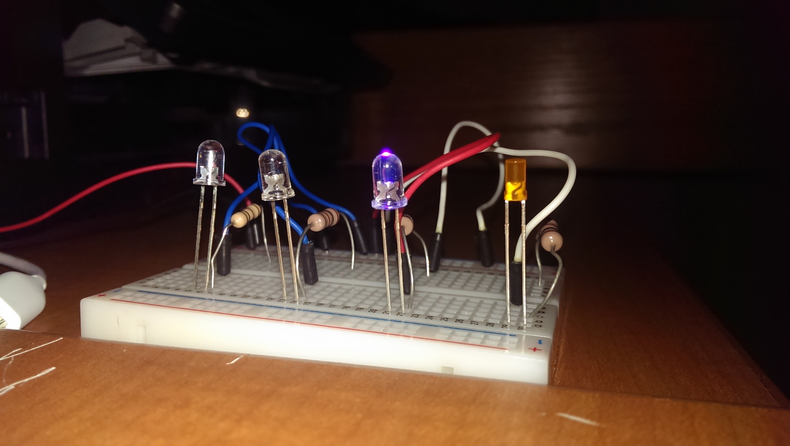
The first prototype was just a breadboard with four LEDs. There was no way of changing color besides manually using a jump cable to power them.
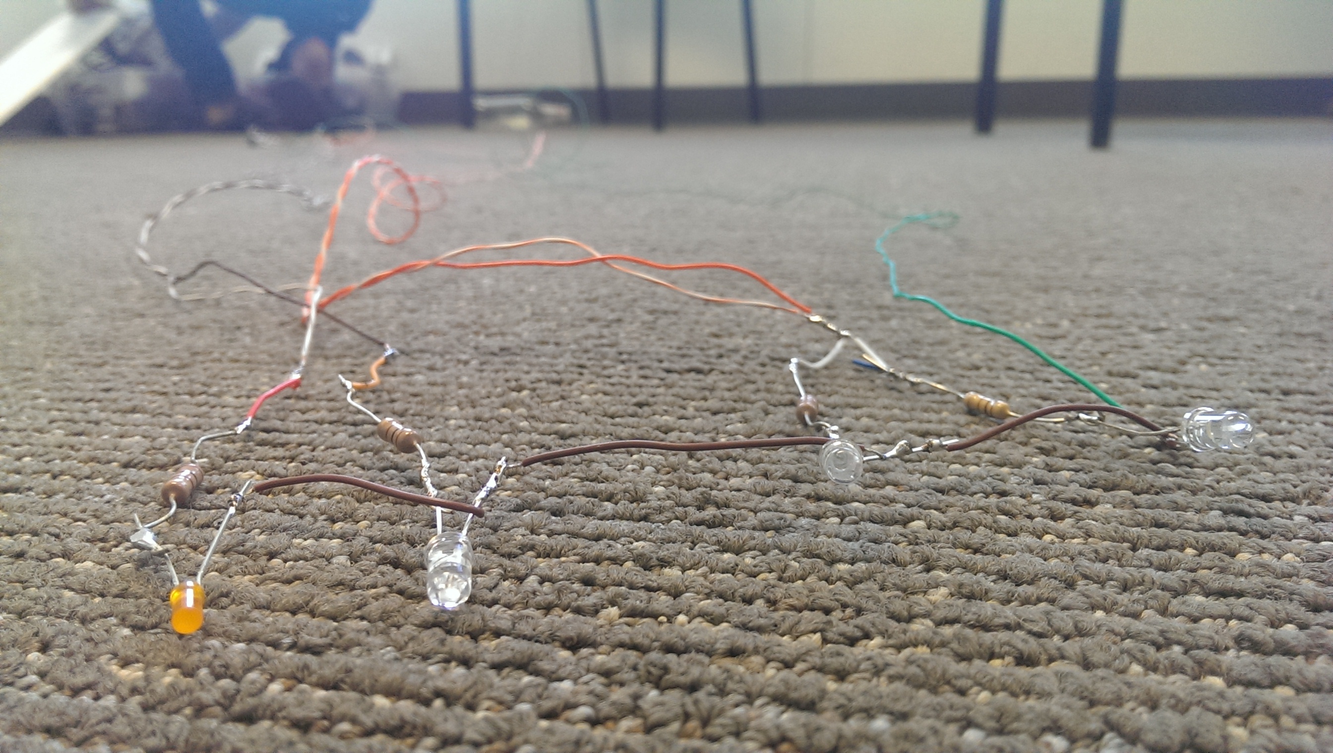
The second prototype did not use a breadboard, instead I soldered the cables to the resistors to the LEDs. The anodes are all soldered together and the cathod so the LEDs are toggled by manually providing power to the desired LED.
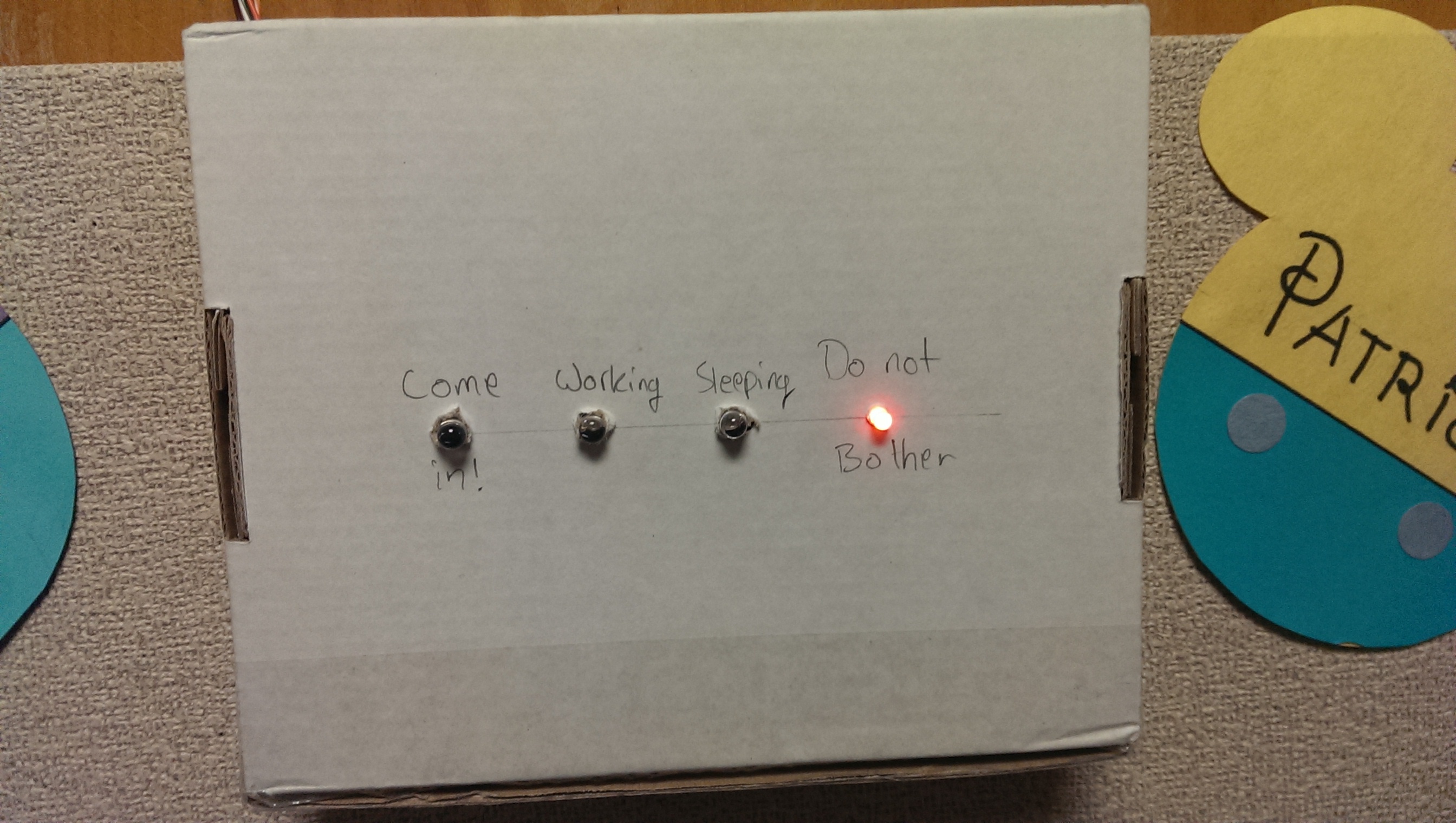
The third prototype was housed in a cardboard box, the cables to power the LEDs would go over and around the door to the inside of the room where I could control which lights turn on.
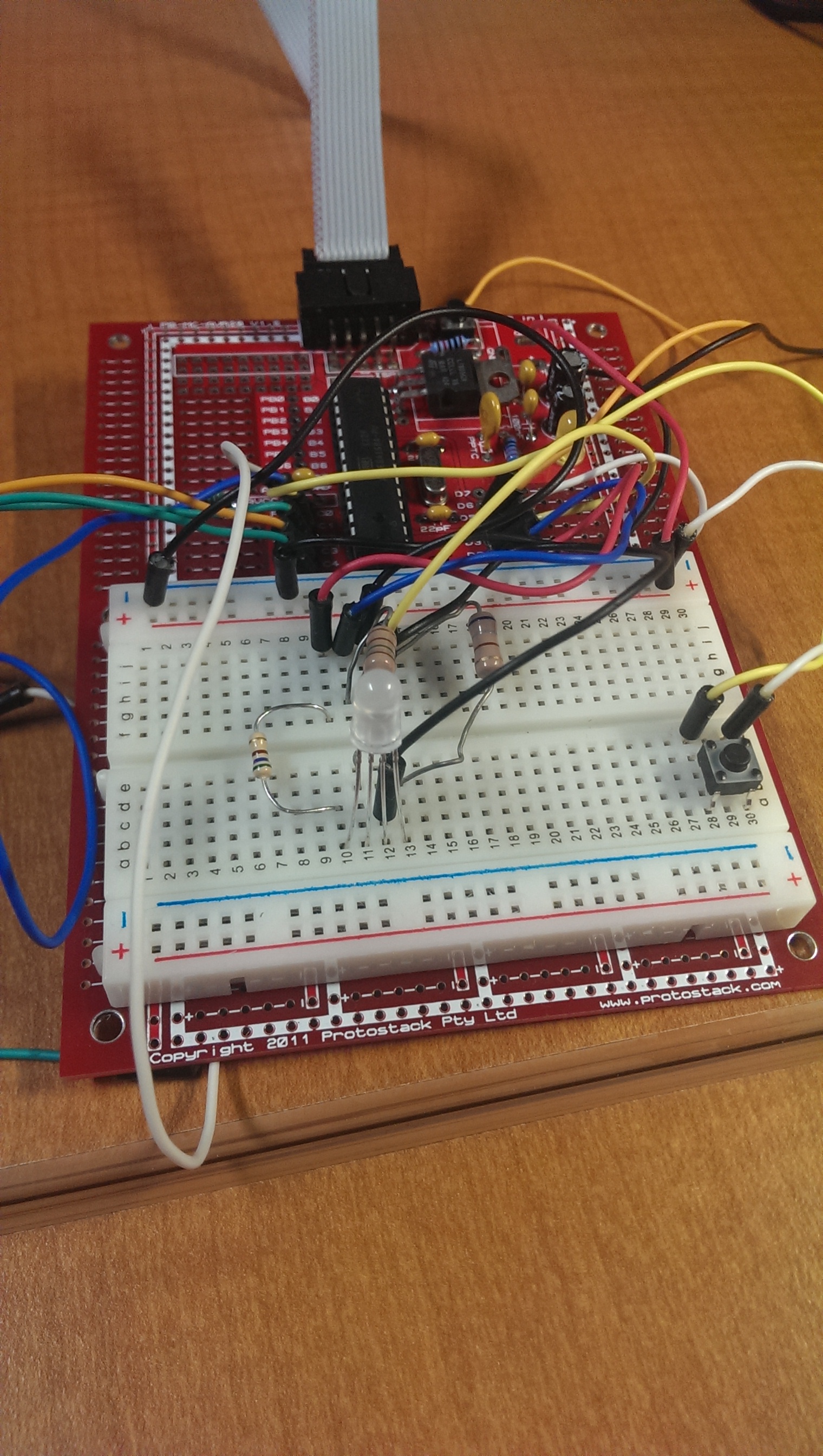
The fourth prototype uses an ATMega168, a push button, and an RGB LED. The button iterates through the various preset colors on the LED.
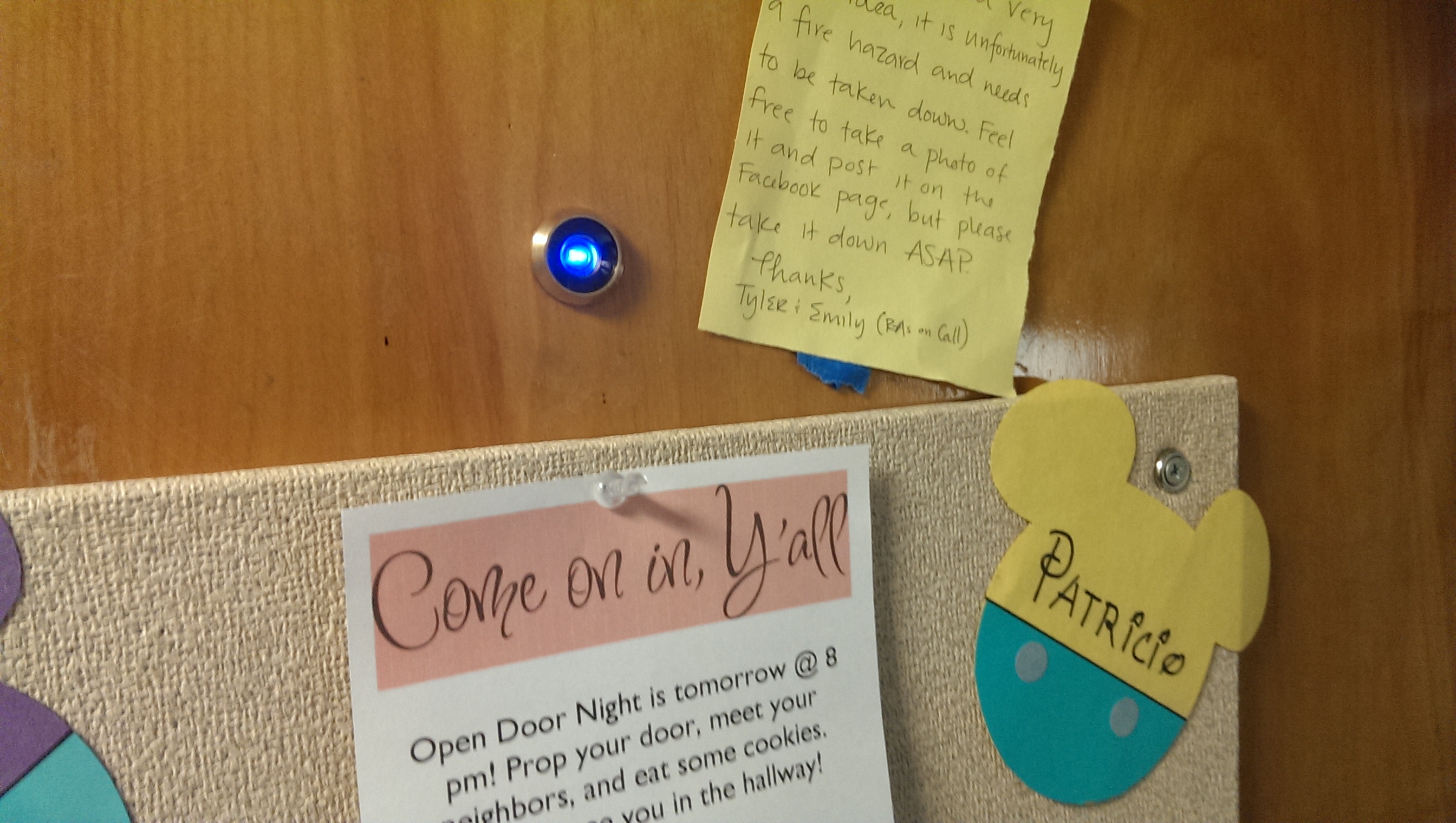
 This is how it looks on the other side of the door.
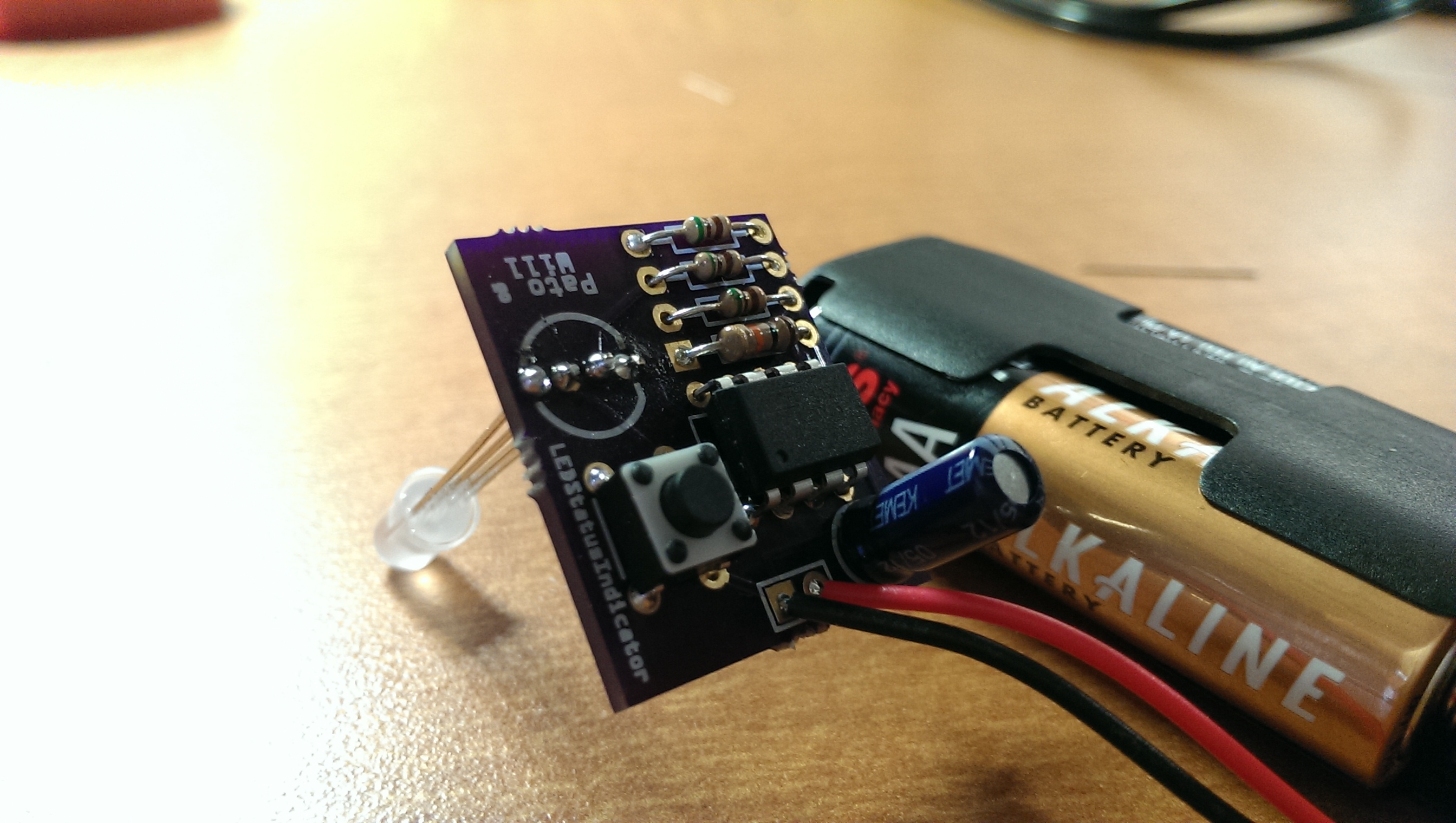
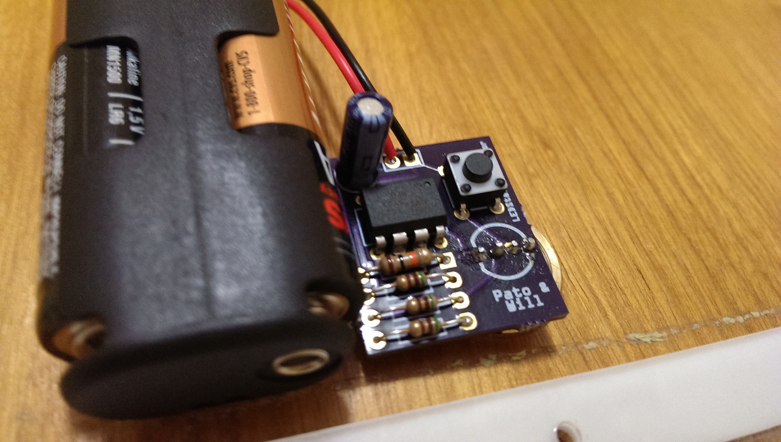
The goal of the fifth protype was to reduce parts, size, and costs, as well as make it battery powered. We used an ATTiny45, a capacitor, four resistors, a push button, jumper cables, and RGB LED.
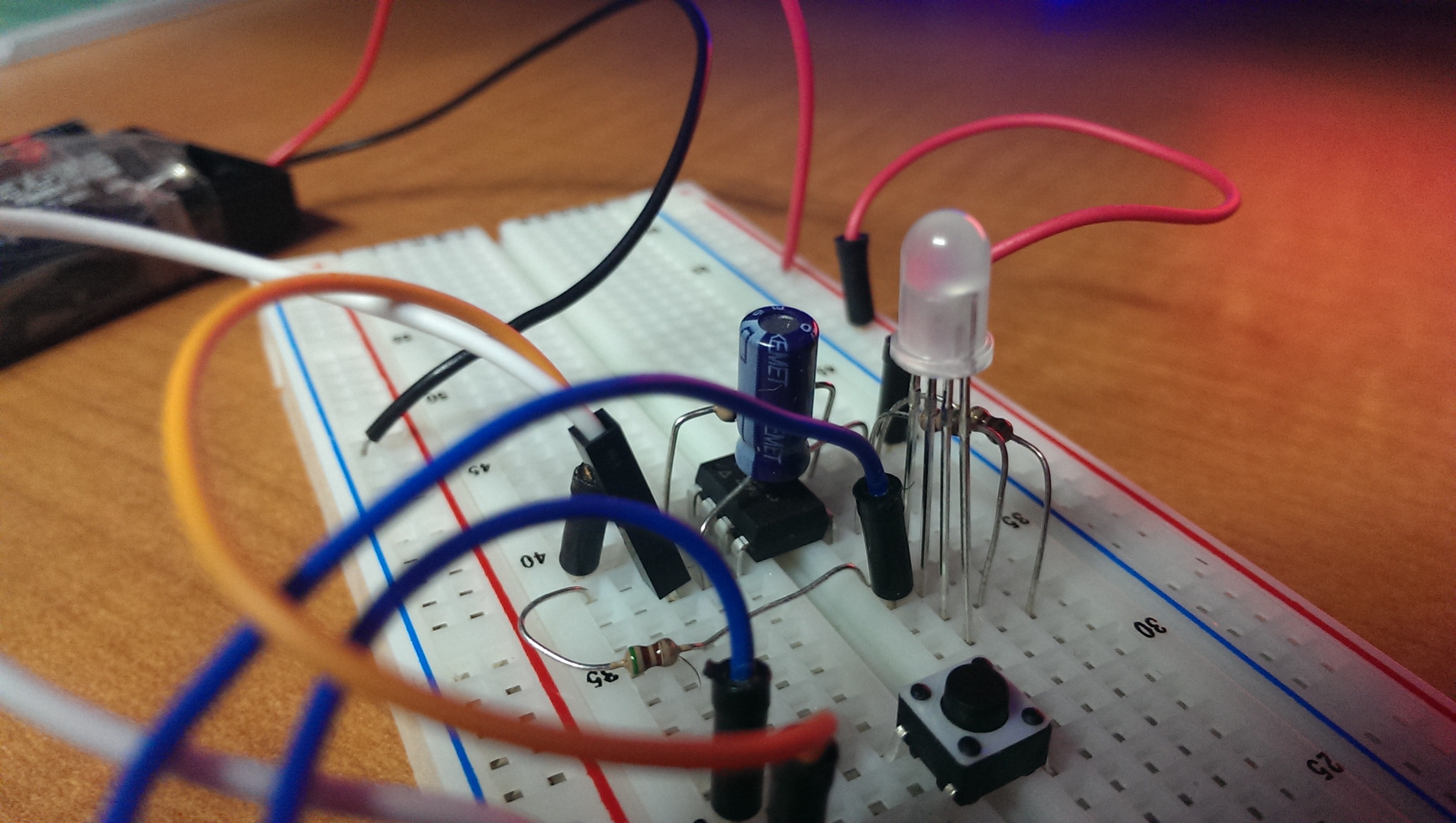 In order to make it battery powered, we drastically reduced the frequence of the internal oscillator as well as made the LED pulse at interval instead of constnatly on.
The PCB boards from our friends at Oshpark! (PS: They're awesome!)
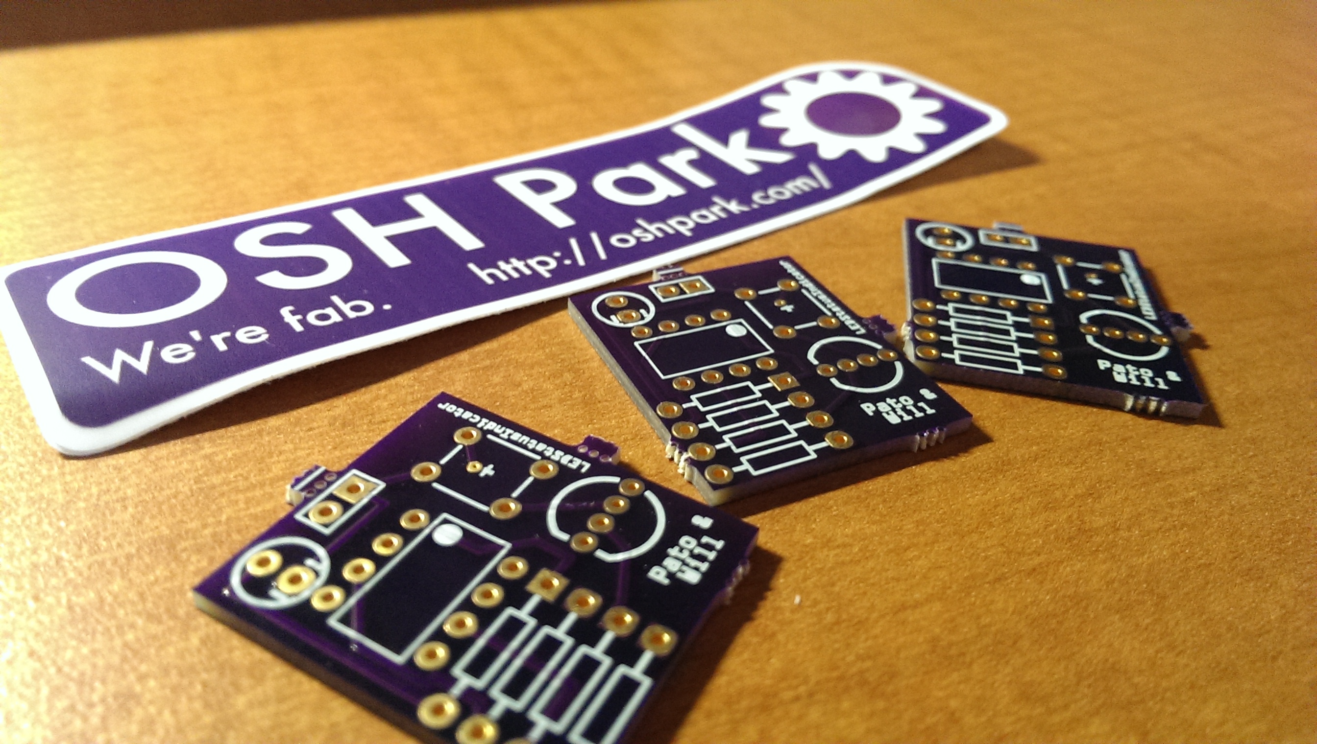
From the backside
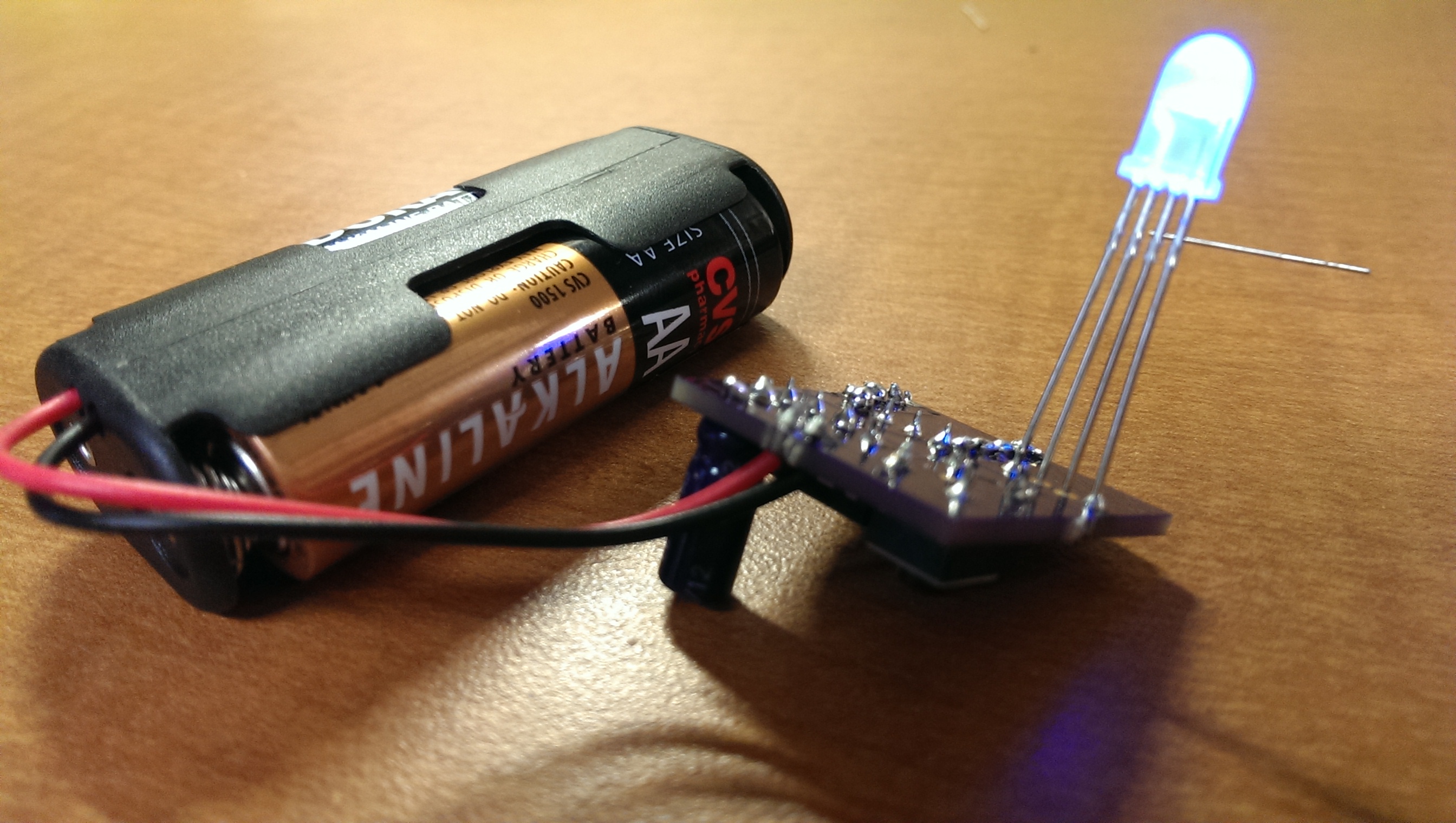
From the front side
Here's how it looks mounted on the door!
| Qty | Value | Footprint | References |
|---|---|---|---|
| 4 | R | R3 | R1, R2, R3, R4 |
| 2 | CONN_1 | PINTST | P1, P2 |
| 2 | SW_PUSH | SW_PUSH_SMALL | SW1, SW2 |
| 1 | ATTINY25-P | DIP-8__300 | IC1 |
| 1 | LED_RCBG | LED5_RGB | LED1 |
| 1 | P*** | 1pin | 1PIN |
It measures 10.2 × 46.7 mm and has 2 copper layers, 1.6 mm thick.
11 parts. The full list of its parts is on this page, with links to each part's symbol and footprint where PCBKit's library has them.
From the pato/LEDStatusIndicator repository on GitHub, at the commit this page was made from: the board is PCB/ledstatusindicator2.kicad_pcb. PCBKit opens the board in the browser, with nothing to install.
Its repository states no licence, so its author keeps all rights: ask pato before reusing the design.
google/mozc-devices
Circuit diagrams and firmware source code for Gboard DIY keyboards


FrameworkComputer/ExpansionCards
Reference designs and documentation to create Expansion Cards for the Framework Laptop

hoglet67/RGBtoHDMI
Bare-metal Raspberry Pi project that provides pixel-perfect sampling of Retro Computer RGB/YUV video and conversion to HDMI

hackclub/OnBoard
💡 Join 1,000 teenagers and make your first PCB with a $100 grant!


tardate/LittleArduinoProjects
a collection of "Little Electronic & Arduino Projects", most involving electronics or an Arduino in one way or another!

basilfx/TRADFRI-Hacking
Hacking IKEA TRÅDFRI products, such as light bulbs, window blinds and other accessories.