2 layers174 × 58 mm
Breakout 112pin Connector
rusefi/rusefi
rusefi - GPL internal combustion engine control unit
42 parts1.2k
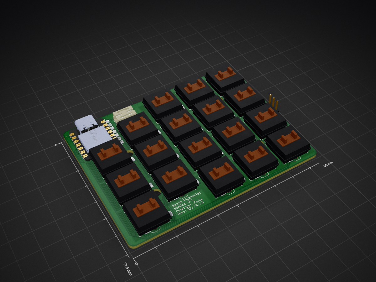
 ParksDevelopment/PickPocket9
The PickPocket is a revamped version of my contest entry keyboard the 2Pocket. When I started making the list of changes I wanted to make it became clear to me I wanted to make a new project from the ground up, so…
PickPocket is an open-source printed circuit board by ParksDevelopment, from the ParksDevelopment/PickPocket repository on GitHub, published under the MIT licence. It is a 2-layer board of 95 × 71.5 mm with 42 parts on 48 nets, routed with 472 tracks and 63 vias.
Its parts include 19 diodes, 3 connectors and 2 ICs. It belongs with the nRF52 and nRF5x boards of this library.

The PickPocket is a revamped version of my contest entry keyboard the 2Pocket. When I started making the list of changes I wanted to make it became clear to me I wanted to make a new project from the ground up, so despite thier similarities the PickPocket is a brand new project with the following features and changes from 2Pocket
Features
Changes from 2Pocket
The main goal of all these changes was to make something I could bring into work, was sturdy enough to be moved around, and solved my biggest frusteration with split keyboards which is charging them.
This project is both not for a contest and much simpler so I will briefly touch on the production and related information. Below is the Item list
| Part Name | Quantity | Solder by hand |
|---|---|---|
| 1N4148 Diode | 38 | NO |
| 2 pin Jst socket | 2 | YES |
| Choc hotswap sockets | 36 | YES |
| Xiao NRF52840 | 2 | YES |
| EEMB Lithium Polymer Battery 3.7V 1100mAh | 2 | DNA |
| Magnetic Connector - Right Angle Three Contact Pins | 2 | YES |
The PCB has a footprint of 95mm x 71.5mm x 1.6mm and is reversable so the cost of production is quite small. It also features 4 mounting holes that are small enough to fit between the keys and are intended for M2 screws. Some things to note if you plan on making one is that to accomadate for the small size the parts that are hand soldered will always be on the bottom of their respective side. This means that you will want to put the micro controller on the bottom of each board. The wiring will work with it on the top but it will overlap with some of the keys. Same goes for the magnetic push pins. There are also 2 spots for the jst connectors. this is so they can be mounted on the bottom and still allow for the same ground power set up of a battery.

Due to the lack of a ADXL345 there is not much need for any firmware changes. Anything that works with a Xiao NRF52840 will work with this as long at it has bluetooth support
There are 2 pins, 4 and 5, which are also the I2C pins that go unused, for now. if you want to add the pedometer back in there is room for it through these. Row Pins: 0,1,2,3 Column Pins: 6,7,8,9,10
The Case isn't anything special but I am happy with how it came out. Because of the extra space I have not working in the constraints of the contest I was able to get something a lot more sturdy. It is reversable like the board so 2 pieces each, a plate and the bottom. It also requires some threaded inserts but those can be easily removed. As it stands only the left side has a reset button.
Much happier with the case this time around and while it still has quirks I don't feel the need to change it that much. I am using the keyboard to go to work and I never have any concerns throwing it in a bag.

I have been happy with this redesign, while it is sad to lose the ADXL345, since there is a lot I was hoping to do with it and it was one of the more unique parts of the first board, it definetly made the project more streamlined, cheaper, and approachable. The pass through charging can not be understated for the impact it has made on my desire to make the board. The whole thing having "one" battery makes it much easier to work with. This is probably my last project with this form factor for a while, not because I don't like it but because I nailed what I was looking for with this one and don't have a whole lot I would want to change. Was told by multiple people it looks like legos, ie the photos.
If you enjoyed or found and of the information helpful consider Buying me a coffee to keep working on projects like this!

| Qty | Value | Footprint | References |
|---|---|---|---|
| 18 | D_Small | Diode_SMD:D_SOD-123 | D1, D2, D3, D4, D5, D6, D10, D11, D12, D13, D14, D15, D16, D17, D18, D19 +2 |
| 18 | MX-NoLED | keyswitches:Kailh_socket_PG1350_reversible | MX1, MX2, MX3, MX4, MX5, MX6, MX10, MX11, MX12, MX13, MX14, MX15, MX16, MX17, MX18, MX19 +2 |
| 2 | Conn_01x02 | Connector_JST:JST_PH_S2B-PH-K_1x02_P2.00mm_Horizontal | J1, J2 |
| 2 | Seeed Studio XIAO nRF52840 | Seeed Studio XIAO Series Library:XIAO-nRF52840-Sense-14P-2.54-21X17.8MM | U1, U2 |
| 1 | Conn_01x03 | Connector_PinHeader_2.54mm:PinHeader_1x03_P2.54mm_Vertical | J3 |
| 1 | D_Schottky | Diode_SMD:D_SMA | D7 |
It measures 95 × 71.5 mm and has 2 copper layers, 1.6 mm thick.
42 parts. The full list of its parts is on this page, with links to each part's symbol and footprint where PCBKit's library has them.
From the ParksDevelopment/PickPocket repository on GitHub, at the commit this page was made from: the board is PCB/PCB.kicad_pcb and its schematic PCB/PCB.kicad_sch. PCBKit opens the board in the browser, with nothing to install.
Its repository publishes it under the MIT licence: you may reuse it on that licence's terms (keep the author's notice, and for a copyleft licence share your changes alike).
rusefi/rusefi
rusefi - GPL internal combustion engine control unit


hackclub/sprig
🍃 Learn to code by making games in a JavaScript web-based game editor.

jamro/tiny-engineer
A small desktop robot that brings an AI coding assistant to life, physically acting out when it reads files, thinks, writes code, and finishes work.

hoglet67/RGBtoHDMI
Bare-metal Raspberry Pi project that provides pixel-perfect sampling of Retro Computer RGB/YUV video and conversion to HDMI

hackclub/OnBoard
💡 Join 1,000 teenagers and make your first PCB with a $100 grant!

