
2 layers64 × 39 mm
SigmaLink USBi
freeDSP/SigmaLink-USBi
The freeDSP SigmaLink USBi PROGRAMMER is an all-in-one real-time programming interface.
31 parts33CC-BY-SA-4.0

 parasyte/GlitchBob-LPC4
Voltage glitching automation tool to break protection on NXP LPC microcontrollers.
GlitchBob LPC is an open-source printed circuit board by parasyte, from the parasyte/GlitchBob-LPC repository on GitHub, published under the MIT licence. It is a 2-layer board of 58.9 × 40.9 mm with 12 parts on 69 nets, routed with 111 tracks and 10 vias.
It is built around the 74LVC1G3157 and 74LVC2G66DP. Its parts include 4 connectors, 3 resistors and 3 ICs. It belongs with the NXP (LPC, Kinetis, i.MX RT) boards of this library.
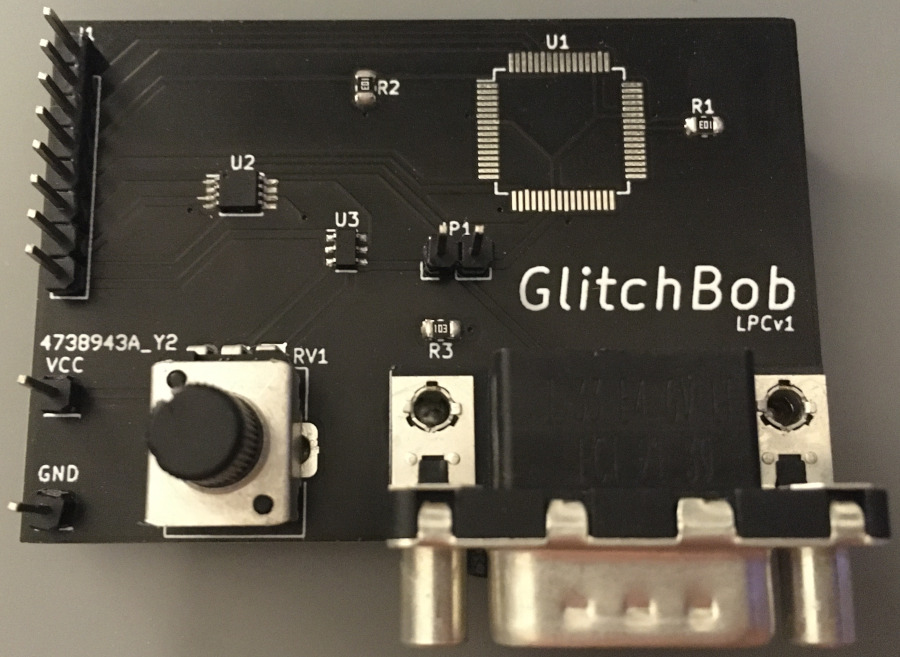
Voltage glitching automation tool to break protection on NXP LPC microcontrollers.
The glitch circuit can be controlled by a Raspberry Pi Pico or other low-cost development board.
These are issues identified in the prototype:
74LVC1G3157 switch input.74LVC2G66 switch inputs.R3 is a bit too close to the serial port.
R3 so it is more easily reachable for assembly.And this is a wish-list for improvements:
74LVC244 or 74HC244 - Octal buffer/line-driver.74LV4052 or 74HC4052 - 4-channel analog multiplexer/demultiplexer.LTC-5723HR - 4-digit 7-segment display with common cathode.VRL.VRL with TLA2021 - 12-bit ADC, I2C.PEC12R-4215F-S0024 - Contact incremental encoder with switch, 2-bit quadrature code, 24 pulses per rotation.1106 Knob for encoder, black and blue.MCP47CVB21 - 12-bit DAC, I2C.VRL/4096 (limited by DAC resolution).| Qty | Value | Footprint | References |
|---|---|---|---|
| 3 | 10K Ohm | Resistor_SMD:R_0805_2012Metric | R1, R2, R3 |
| 2 | Conn_01x01 | Connector_PinHeader_2.54mm:PinHeader_1x01_P2.54mm_Vertical | J3, J4 |
| 1 | 10K Ohm | Potentiometer_THT:Potentiometer_Alps_RK09K_Single_Vertical | RV1 |
| 1 | 74LVC1G3157 | Package_SO:TSOP-6_1.65x3.05mm_P0.95mm | U3 |
| 1 | 74LVC2G66 | Package_SO:TSSOP-8_3x3mm_P0.65mm | U2 |
| 1 | Conn_02x04_Odd_Even | Connector_PinHeader_2.54mm:PinHeader_1x08_P2.54mm_Vertical | J1 |
| 1 | DB9_Male | Connector_Dsub:DSUB-9_Male_Horizontal_P2.77x2.84mm_EdgePinOffset7.70mm_Housed_MountingHolesOffset9.12mm | J2 |
| 1 | Jumper_2_Bridged | Connector_PinHeader_2.54mm:PinHeader_1x02_P2.54mm_Vertical | JP1 |
| 1 | LPC2142FBD64 | Package_QFP:LQFP-64_10x10mm_P0.5mm | U1 |
freeDSP/SigmaLink-USBi
The freeDSP SigmaLink USBi PROGRAMMER is an all-in-one real-time programming interface.

1847123212/vl670
VL670/VL671 Development Board - USB 2.0 to 3.0 Transaction Translator ======================================================================


GoldenExperienceR/EEE3088F-Project-PCB-Files-Group-36-TRKJON002-MTMTAD006
EEE3088F Project Power PCB KiCad Design

super-cow-powers/better-lamp-controller
A custom lamp controller with audio, controlled with an RP2040


It measures 58.9 × 40.9 mm and has 2 copper layers, 1.6 mm thick.
12 parts, built around the 74LVC1G3157 and 74LVC2G66DP. The full list of its parts is on this page, with links to each part's symbol and footprint where PCBKit's library has them.
From the parasyte/GlitchBob-LPC repository on GitHub, at the commit this page was made from: the board is board/GlitchBob LPC.kicad_pcb and its schematic board/GlitchBob LPC.kicad_sch. PCBKit opens the board in the browser, with nothing to install.
Its repository publishes it under the MIT licence: you may reuse it on that licence's terms (keep the author's notice, and for a copyleft licence share your changes alike).