2 layers101.5 × 25.5 mm

 Pakue95/VFD_Watch41
Portable VFD based on IVL2-7/5 and ESP32
VFD Watch is an open-source printed circuit board by Pakue95, from the Pakue95/VFD_Watch repository on GitHub. It is a 2-layer board of 67.8 × 55 mm with 67 parts on 113 nets, routed with 632 tracks and 142 vias.
It is built around the ESP32-WROOM-32, DRV8837CDSG and FT231XS-R, with the MCP1663-E/OT, TBD62783APG and MIC5219-3.3YM5 among its other parts. Its parts include 19 capacitors, 19 resistors, 10 ICs, 4 switches and 2 connectors. It belongs with the lEDs and displays and wearables boards and the ESP32 boards of this library.


This project was originally inspired by Johngineer's ChronodeVFD project. However no concrete design information were available therefore this project was born.
The goal was to create a mobile driver circuit for the common IVL2-5/7 vacuum fluorescent display, that is powered by a single cell battery. The datasheet of the display can be found on the Loststreak blog.
An ESP32 WROOM-32 module is used as a microcontroller for the display and wireless communication. It is interfaced fo r programming via a FT231XS USB-Serial converter.
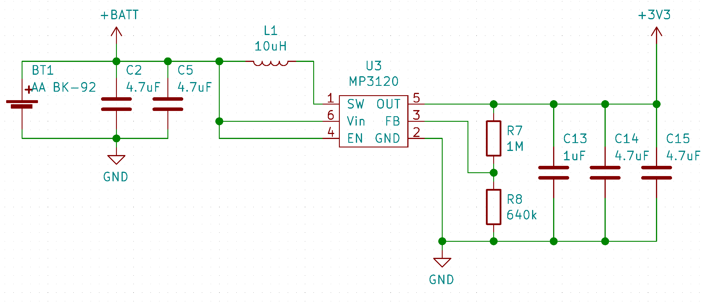
The choice for the battery driver IC fell on the MP3120 single cell 1.2A step up module as it can handle very low battery voltages and still start up. If wireless communication is used during the power up of the display the step-up module won't be able to supply enough power from a normal Alkaline cell to the ESP32 and a brownout reset will occur. Primary lithium cells, 2 Alkaline batteries or LiIon should be sufficient to power all functions at the same time.
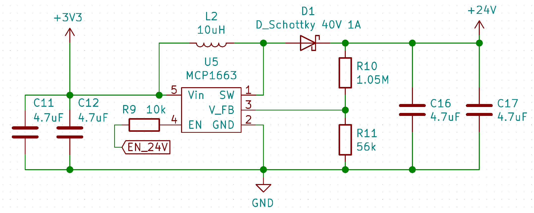
The display is driven by a 24V rail from a MCP1663 step-up converter and high-side switches (TBD62783A) to power the segments. The filament is driven from the 3.3V rail and pulse-modulated from a motor H-bridge driver (DRV8837C) to achieve an equivalent to the 2.4V @ 60mA power conditions described in the datasheet. The H-bridge design allows an equal brightness of the characters without the use of a complex center-tapped AC circuit.
void begin(uint8_t dutyCycle, uint32_t freqMultiplex, uint32_t freqHeat)dutyCycle sets the PWM duty cycle of the heating filament. 0-255; typical 120.freqMultiplex sets the rate at which the characters are cycled though (1kHz -> 200Hz total refresh of the display). The timing is controlled in the background by an interrupt function that calls for an update of the currently displayed character. This process runs on core 0 of the ESP32, therefore during WiFi use the display can flicker a bit.freqHeat sets the frequency of the heating filament PWM. The value should be in the kHz range.void deactivate()Turns of the heating filament and the 24V rail to preserve power.
void activate()Turns the display back on after a deactivate().
void setHours(uint8_t hours)Sets the first two digits. Range 0-99.
void setMinutes(uint8_t minutes)Sets the last two digits. Range 0-99.
void setCharacter(char character, int pos)Displays a char (a-z; 0-9; '-') at position pos (0-3)
void print(char* text)Similar to setCharacter() but it displays the first 4 chars of the array.
void setSegment(uint8_t segments, uint8_t pos);Sets specific segments of a digit through the use of a byte mask (least to most significant bit). E.g. 0b00101000 would set segments d & f. pos declares the digit to be changed (0-3).
| Qty | Value | Footprint | References |
|---|---|---|---|
| 11 | 10k | Resistor_SMD:R_0805_2012Metric | R5, R6, R9, R12, R13, R14, R15, R16, R17, R18, R19 |
| 11 | 4.7uF | Capacitor_SMD:C_0805_2012Metric | C1, C2, C5, C6, C8, C11, C12, C14, C15, C16, C17 |
| 3 | 100nF | Capacitor_SMD:C_0805_2012Metric | C9, C10, C18 |
| 2 | 0R | Resistor_SMD:R_1206_3216Metric | R1, R2 |
| 2 | 10uH | Inductor_SMD:L_Taiyo-Yuden_MD-5050 | L1, L2 |
| 2 | 27 | Resistor_SMD:R_0805_2012Metric | R3, R4 |
| 2 | 47pF | Capacitor_SMD:C_0805_2012Metric | C3, C4 |
| 2 | TBD62783A | Package_SO:SOP-18_7.0x12.5mm_P1.27mm | U8, U9 |
| 1 | 1.05M | Resistor_SMD:R_0805_2012Metric | R10 |
| 1 | 10uF | Capacitor_SMD:C_1206_3216Metric | C19 |
| 1 | 1M | Resistor_SMD:R_0805_2012Metric | R7 |
| 1 | 1uF | Capacitor_SMD:C_0805_2012Metric | C13 |
| 1 | 470pF | Capacitor_SMD:C_0805_2012Metric | C7 |
| 1 | 56k | Resistor_SMD:R_0805_2012Metric | R11 |
| 1 | 640k | Resistor_SMD:R_0805_2012Metric | R8 |
| 1 | AA BK-92 | VFD_Watch:BK-92 | BT1 |
| 1 | B1 | Button_Switch_SMD:SW_SPST_EVQP7A | SW1 |
| 1 | B2 | Button_Switch_SMD:SW_SPST_EVQP7A | SW2 |
| 1 | B_0 | Button_Switch_SMD:SW_SPST_EVQP7A | SW4 |
| 1 | B_RES | Button_Switch_SMD:SW_SPST_EVQP7A | SW3 |
| 1 | DRV8837C | Package_SON:WSON-8-1EP_2x2mm_P0.5mm_EP0.9x1.6mm | U2 |
| 1 | D_Schottky 40V 1A | Diode_SMD:D_SOD-323 | D1 |
| 1 | ESP32-WROOM | ESP32-footprints-Lib:ESP32-WROOM | U6 |
| 1 | FT231XS | Package_SO:SSOP-20_3.9x8.7mm_P0.635mm | U4 |
| 1 | I2C_Con | Connector_PinHeader_1.27mm:PinHeader_1x04_P1.27mm_Vertical | J2 |
| 1 | IVL2-7_5 | VFD_Watch:ILV2-5_7 | U10 |
| 1 | MBT3904DW1 | Package_TO_SOT_SMD:SOT-363_SC-70-6 | Q1 |
| 1 | MCP1663 | Package_TO_SOT_SMD:TSOT-23-5 | U5 |
| 1 | MCP23017_SS | Package_SO:SSOP-28_5.3x10.2mm_P0.65mm | U7 |
| 1 | MIC5219-3.3YM5 | Package_TO_SOT_SMD:SOT-23-5 | U1 |
| 1 | MP3120 | Package_TO_SOT_SMD:TSOT-23-6 | U3 |
| 1 | USB_B_Micro | Connector_USB:USB_Micro-B_Molex_47346-0001 | J1 |
The 59 most common of 67 parts.
It measures 67.8 × 55 mm and has 2 copper layers, 1.6 mm thick.
67 parts, built around the ESP32-WROOM-32, DRV8837CDSG, FT231XS-R and MCP1663-E/OT. The full list of its parts is on this page, with links to each part's symbol and footprint where PCBKit's library has them.
From the Pakue95/VFD_Watch repository on GitHub, at the commit this page was made from: the board is VFD_Watch.kicad_pcb. PCBKit opens the board in the browser, with nothing to install.
Its repository states no licence, so its author keeps all rights: ask Pakue95 before reusing the design.


cyrillvalentini/SAP-Extended
Extended Simple-As-Possible Computer based on Ben Eaters video series
