
4 layers52 × 27 mm
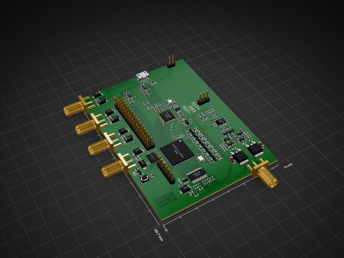
Now your computer can make waves
Awg1 is an open-source printed circuit board by Oscilllator, from the Oscilllator/waveform-generator repository on GitHub. It is a 6-layer board of 74 × 99.7 mm with 235 parts on 311 nets, routed with 1,356 tracks and 640 vias.
It is built around the TLV62569DRL, AD9744AR and W25Q128JVPIQ, with the 93LC56BT-I/OT, FT232H and X252012MMB4SI-24 among its other parts. Its parts include 90 resistors, 74 capacitors, 22 diodes, 17 transistors and 12 ICs. It belongs with the FPGA and CPLD boards of this library.


The purpose of this waveform generator is to give your computer the ability to make waves. It should be thought of as a waveform interface for your computer, like a network interface or an audio interface. The computer streams waveforms continuously to the generator, the generator itself has no memory. I created this because I don't like the software interface to any other waveform generator I have used.
You use it like this:
import numpy as np
import awglib
awg = awglib.awg()
samples = np.sin(np.linspace(0, 2 * np.pi, 1000))
awg.send_volts(samples)
You can simply stream samples to it, or gate the sending of the samples on a trigger input. It also has two digital outputs which are embedded in the sample stream. You can use them like this:
samples = np.sin(np.linspace(0, 2 * np.pi, 1000))
d0 = samples > 0.8
d1 = samples < -0.5
awg.send_volts(samples, digital=[d0, d1])
Which then would look like this:
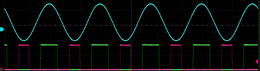
This is useful for triggering your scope or other instruments.
| Parameter | Value |
|---|---|
| Samples rate | 10 MSa/s |
| Rise/fall time | 50 ns |
| Max output current | 600 mA |
| Resolution | 14 bit |
| Digital outputs | 2 |
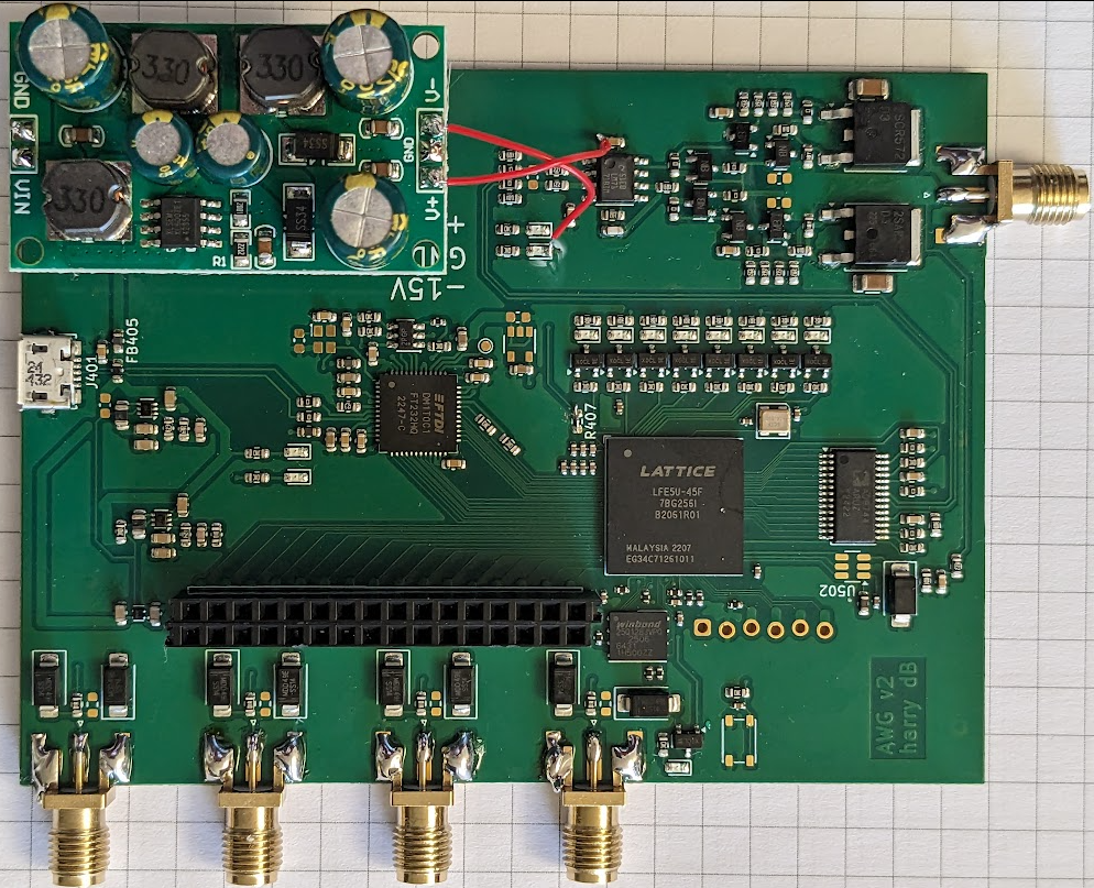
The device also has a 16 bit digital output bus for debugging the fpga, and 8 LED's. The digital outputs come straight from the FPGA and so have no drive strength to speak of. You won't blow up the FPGA if you 50R terminate them, though.
It looks like this:
This example is examples/scrolling_text.py and demonstrates some of the benefits of having a streaming setup - there is a lot of memory on your main computer as compared to any reasonable waveform generator.
This whole gif is one single waveform of about ~500MB over the wire. Several passes are made over the text, one for each letter section. The persistence of vision within the oscilloscope stitches them together, producing whole letters. Once the whole text has been emitted the waveform is then re-emitted with the embedded digital trigger pulse sent with a slightly different time delay. This is easily done by simply concatenating the waveform to itself many times, attaching a shifted version of the trigger array each time. This wastes a lot of memory but was trivial to implement.
The USB chip is a FT232, but I have programmed it to have a custom Vid and Pid, so that the linux kernel doesn't grab it.
This script sets up the udev rules so the device can be opened without root:
./ft/setup.sh
I install it like this from the root directory of the repository:
pip install -e .
That way the library is loaded from the repository on startup rather than being copied to an install directory. Ask your favourite AI what's right for you.
The EEPROM of the FT2332 needs to be programmed so that it will output in synchronous FIFO mode, and so that the default vendor ID and product ID is changed, preventing the linux kernel from recognising it.
./program_eeprom.sh
This repository contains the kicad files, RTL, and API to operate a waveform generator.
I got the PCB's assembled with JLCPCB's 6 layer service with plated over vias, to make the routing of the FPGA BGA package easy. The device uses an FT232 as a USB->FIFO adapter, that currently streams exclusively in the PC->FT232 direction. Use of the device in this mode requires flashing the eeprom, for which a utility is also included.
The Flow of information is as follows:
PC -> FT232 -> ECP5 FPGA -> AD9744 DAC -> Amplifier
The RTL for the fpga is provided, which uses the excellent repository here to interface with the FT232. The AD9744 has a simple parallel interface, so that also makes things easy.
The simulation can be run as a unit test with ./run_tests.sh
The waveform generator is interfaces with in python, though I may port it to C at some point.
This device was designed as a series of sub-boards. It started as a Colorlight DAC dev board and the amplifier stage. These were then merged into a Single PCB. There are various other notes on my lab notes page that detail other parts of the design process.
| Qty | Value | Footprint | References |
|---|---|---|---|
| 28 | 100n | Capacitor_SMD:C_0402_1005Metric | C201, C202, C204, C205, C206, C207, C209, C210, C211, C212, C213, C214, C215, C216, C217, C220 +12 |
| 12 | 10kR | Resistor_SMD:R_0603_1608Metric | R202, R212, R504, R505, R601, R701, R801, R901, R1001, R1101, R1201, R1301 |
| 12 | LED | Diode_SMD:D_0603_1608Metric | D401, D402, D601, D701, D801, D901, D1001, D1101, D1201, D1301, D2001, D2002 |
| 10 | 0 | Resistor_SMD:R_0603_1608Metric | R2003, R2004, R2023, R2024, R2031, R2032, R2034, R2035, R2036, R2037 |
| 10 | 0.1u | Capacitor_SMD:C_0603_1608Metric | C401, C402, C403, C405, C406, C407, C408, C409, C410, C411 |
| 9 | 10K | Resistor_SMD:R_0402_1005Metric | R201, R203, R204, R205, R206, R208, R209, R210, R211 |
| 9 | Q_NMOS_Depletion_GSD | Package_TO_SOT_SMD:SOT-23 | Q201, Q601, Q701, Q801, Q901, Q1001, Q1101, Q1201, Q1301 |
| 9 | SS14 | Diode_SMD:D_SMA | D1401, D1402, D1404, D1501, D1502, D1601, D1602, D1701, D1702 |
| 8 | 10uF | Capacitor_SMD:C_0603_1608Metric | C302, C306, C307, C308, C311, C312, C313, C314 |
| 8 | 300 | Resistor_SMD:R_0603_1608Metric_Pad0.98x0.95mm_HandSolder | R602, R702, R802, R902, R1002, R1102, R1202, R1302 |
| 8 | 4k | Resistor_SMD:R_0603_1608Metric | R2013, R2014, R2015, R2016, R2017, R2018, R2019, R2020 |
| 6 | 10k | Resistor_SMD:R_0603_1608Metric | R408, R409, R410, R411, R2021, R2022 |
| 6 | 4u7 | Capacitor_SMD:C_0402_1005Metric | C203, C208, C218, C219, C227, C228 |
| 5 | 100nF | Capacitor_SMD:C_0603_1608Metric | C2002, C2004, C2009, C2010, C2011 |
| 5 | 4.7u | Capacitor_SMD:C_0603_1608Metric | C404, C412, C413, C414, C415 |
| 5 | DNP | Capacitor_SMD:C_0603_1608Metric | C2001, C2003, C2007, C2008, R305 |
| 5 | IPEX-004 | Connector_Coaxial:SMA_Amphenol_132289_EdgeMount | J1401, J1501, J1601, J1701, J2005 |
| 4 | 0R | Resistor_SMD:R_0603_1608Metric | R407, R501, R502, R503 |
| 4 | 100R | Resistor_SMD:R_0603_1608Metric | R1901, R1903, R1904, R1905 |
| 4 | 2SCR512R | Package_TO_SOT_SMD:SOT-23 | Q2001, Q2003, Q2004, Q2005 |
| 4 | 49.9R | Resistor_SMD:R_0603_1608Metric | R1402, R1502, R1602, R1702 |
| 3 | 100nF | Resistor_SMD:R_0603_1608Metric | C501, C502, C503 |
| 3 | 10K | Resistor_SMD:R_0603_1608Metric | R401, R403, R404 |
| 3 | 50 | Resistor_SMD:R_0603_1608Metric | R2005, R2006, R2010 |
| 3 | BLM18HE152SN1D | Inductor_SMD:L_0603_1608Metric | FB402, FB403, FB404 |
| 2 | 1.5 | Resistor_SMD:R_0603_1608Metric | R2027, R2028 |
| 2 | 100 | Resistor_SMD:R_0603_1608Metric | R2025, R2026 |
| 2 | 10pF | orange_cram:C_0603_1608Metric | C309, C310 |
| 2 | 2.2uH | Inductor_SMD:L_0805_2012Metric | L302, L303 |
| 2 | 225 | Resistor_SMD:R_0603_1608Metric | R2007, R2008 |
| 2 | 22uF | Capacitor_SMD:C_1206_3216Metric | C2005, C2006 |
| 2 | 2SAR512R | Package_TO_SOT_SMD:SOT-23 | Q2002, Q2006 |
| 2 | MF-FSMF035X-2 | Inductor_SMD:L_0603_1608Metric | FB401, FB405 |
| 2 | TLV62569DRL | Package_TO_SOT_SMD:SOT-563 | U303, U304 |
| 1 | 100k | Capacitor_SMD:C_0603_1608Metric | R306 |
| 1 | 10k | Capacitor_SMD:C_0603_1608Metric | R304 |
| 1 | 120k | Capacitor_SMD:C_0603_1608Metric | R307 |
| 1 | 12K | Resistor_SMD:R_0603_1608Metric | R406 |
| 1 | 16MHz | orange_cram:CDFN_3.2x2.5mm_XO | X201 |
| 1 | 22R | Resistor_SMD:R_0402_1005Metric | R207 |
| 1 | 2SAR572D3TL | Package_TO_SOT_SMD:TO-252-2 | Q2008 |
| 1 | 2SCR572D3TL | Package_TO_SOT_SMD:TO-252-2 | Q2007 |
| 1 | 2k | Resistor_SMD:R_0603_1608Metric | R2029 |
| 1 | 2kR | Resistor_SMD:R_0603_1608Metric | R506 |
| 1 | 2kR | Resistor_SMD:R_0402_1005Metric | R405 |
| 1 | 3.3k | Resistor_SMD:R_0603_1608Metric | R2009 |
| 1 | 360k | Capacitor_SMD:C_0603_1608Metric | R308 |
| 1 | 47589-0001 | Connector_USB:USB_Micro-B_Molex_47346-0001 | J401 |
| 1 | 82k | Capacitor_SMD:C_0603_1608Metric | R309 |
| 1 | 8k | Resistor_SMD:R_0603_1608Metric | R2030 |
| 1 | 93LC56BT-I/OT | vs:SOT-23-6 | U401 |
| 1 | AD9744 | Package_SO:TSSOP-28_4.4x9.7mm_P0.65mm | U501 |
| 1 | ADS7866/CI7476 | Package_TO_SOT_SMD:TSOT-23-6 | U502 |
| 1 | AP2127K-3.3 | vs:SOT-23-5 | U404 |
| 1 | Conn_01x02_Pin | Connector_PinHeader_2.54mm:PinHeader_1x02_P2.54mm_Vertical | J1802 |
| 1 | Conn_01x03_Pin | Connector_PinHeader_2.54mm:PinHeader_1x03_P2.54mm_Vertical | J1801 |
| 1 | Conn_02x16_Odd_Even | Connector_PinHeader_2.54mm:PinHeader_2x16_P2.54mm_Vertical | J201 |
| 1 | DNI | Resistor_SMD:R_0603_1608Metric | R402 |
| 1 | ECP5U_12_CABGA256 | Package_BGA:BGA-256_14.0x14.0mm_Layout16x16_P0.8mm_Ball0.45mm_Pad0.32mm_NSMD | U201 |
| 1 | FT232H | vs:QFN-48-1EP_8x8mm_P0.5mm_EP6.2x6.2mm | U403 |
| 1 | JTAG | josh-connectors:STM_6_PIN_THT_Staggered | J202 |
| 1 | LM7171xIM | Package_SO:SOIC-8_3.9x4.9mm_P1.27mm | U2001 |
| 1 | NCP115-2.5 | Package_SON:Texas_X2SON-4_1x1mm_P0.65mm | U302 |
| 1 | PTS810 | josh-buttons-switches:SW_SPST_PTS810 | SW201 |
| 1 | Pink | LED_SMD:LED_0603_1608Metric | D201 |
| 1 | TestPoint | TestPoint:TestPoint_Pad_D1.0mm | TP401 |
| 1 | W25Q128JVPIQ | josh-soic-sot-etc:WSON-8-1EP_6x5mm_P1.27mm_EP3.4x4.3mm | U202 |
| 1 | X252012MMB4SI | vs:Oscillator_SMD_Abracon_ASDMB-4Pin_2.5x2.0mm | U402 |
It measures 74 × 99.7 mm and has 6 copper layers, 1.6 mm thick.
235 parts, built around the TLV62569DRL, AD9744AR, W25Q128JVPIQ and 93LC56BT-I/OT. The full list of its parts is on this page, with links to each part's symbol and footprint where PCBKit's library has them.
From the Oscilllator/waveform-generator repository on GitHub, at the commit this page was made from: the board is hardware/awg2/awg1.kicad_pcb and its schematic hardware/awg2/AD9744.kicad_sch. PCBKit opens the board in the browser, with nothing to install.
Its repository states no licence, so its author keeps all rights: ask Oscilllator before reusing the design.


NoBlackBoxes/LastBlackBox
A course for brains interested in brains (not tools interested in tools)

tinyvision-ai-inc/pico2-ice
Doc | Hardware | SDK | Schematic | Assembly | Discord