
4 layers135.1 × 56.9 mm

 open-batt/openbms-hardware4
OpenBMS - Open Source Battery Management System Hardware
Openbms is an open-source printed circuit board by open-batt, from the open-batt/openbms-hardware repository on GitHub, published under the MIT licence. It is a 4-layer board of 68.4 × 52.4 mm with 220 parts on 172 nets, routed with 2,002 tracks and 418 vias.
It is built around the TPS12000QDGXRQ1, 2N7002KW and BSS84AKW,115-VB, with the NTMFS5C612NLT1G and BAT54J among its other parts. Its parts include 119 resistors, 45 capacitors, 21 ICs, 15 diodes and 7 transistors. It belongs with the power boards and the STM32 boards of this library.





OpenBMS is an open-source battery management system for 2 to 7-cell Li-Ion and Li-Po battery packs. A fully integrated hardware and firmware solution for battery management and protection, providing:
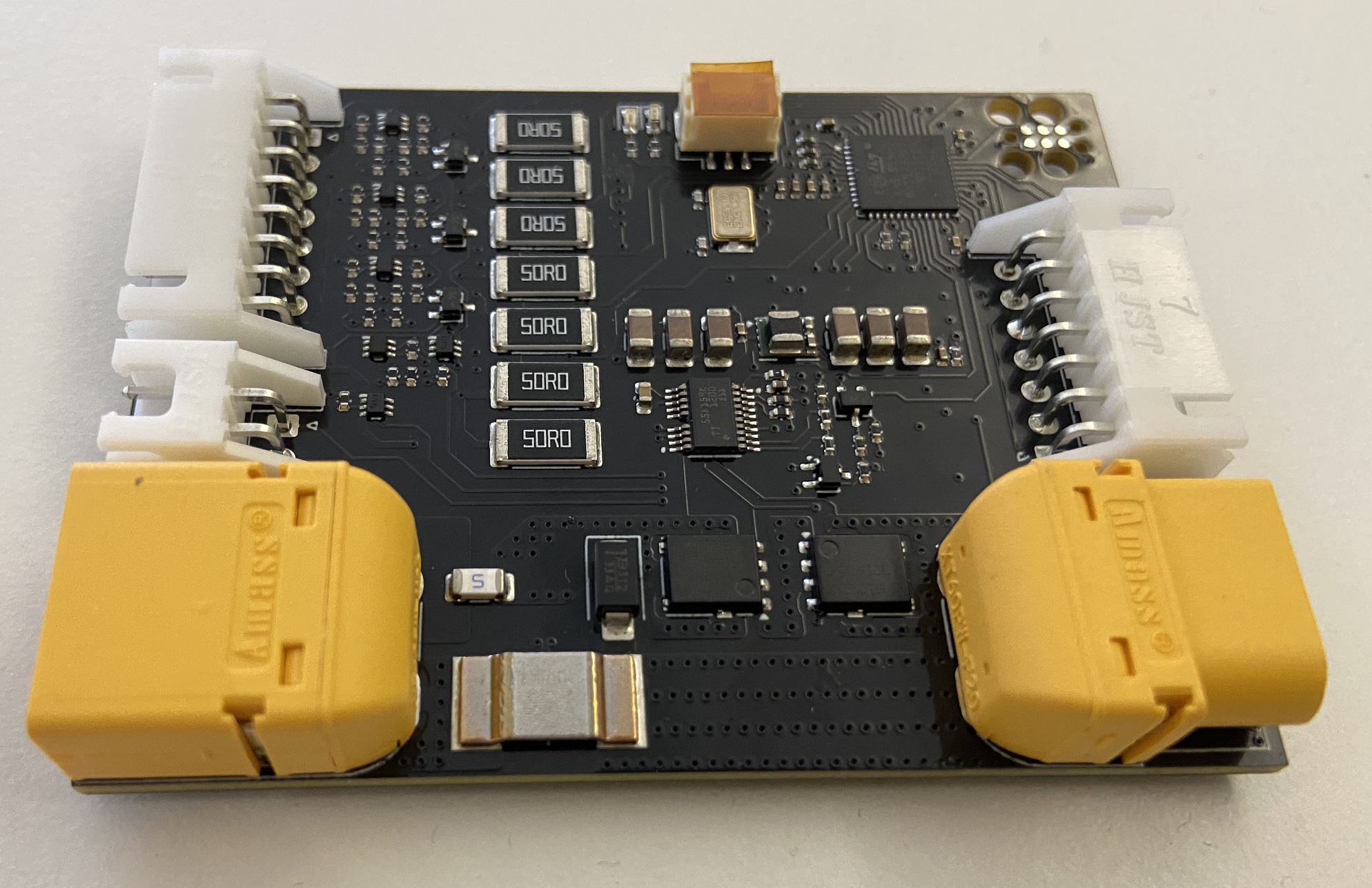 | 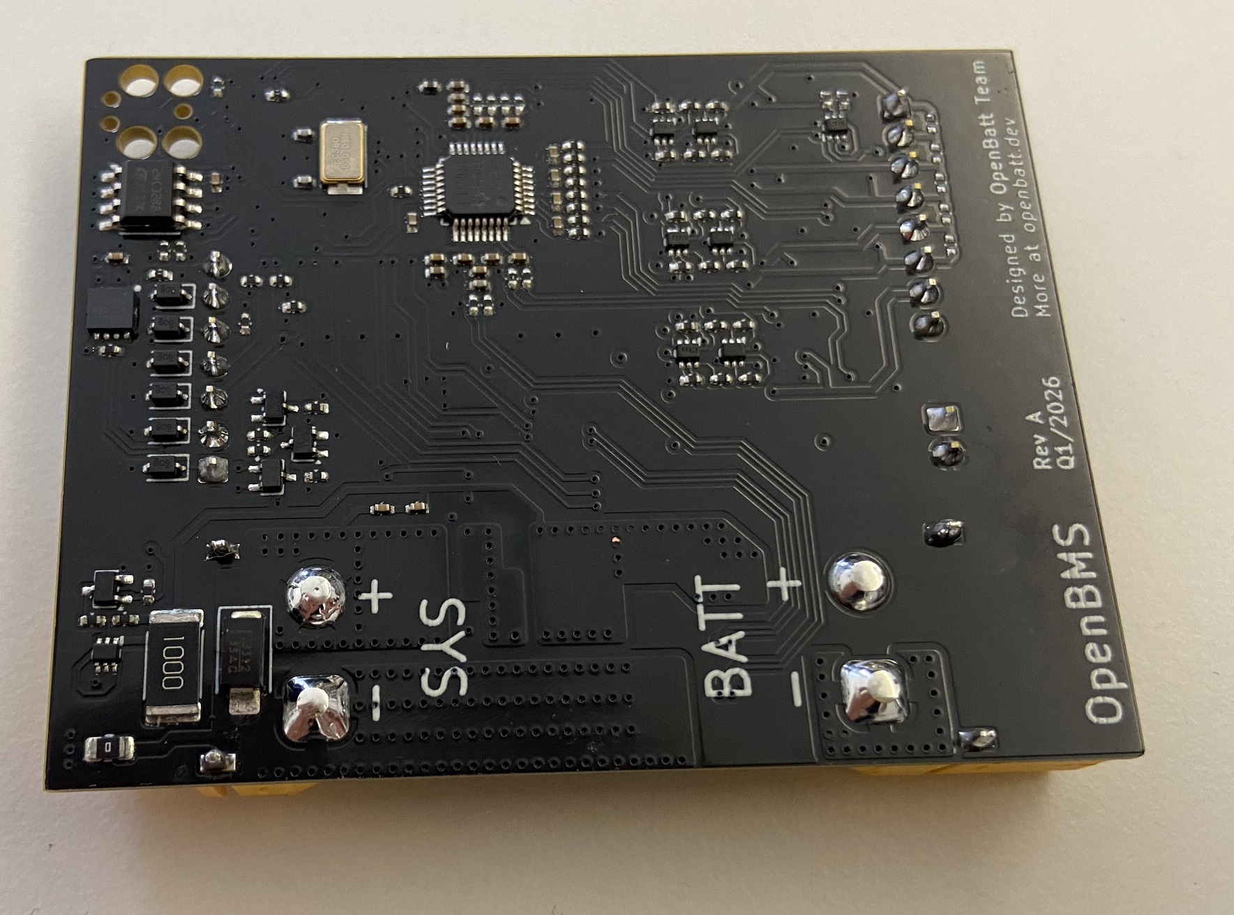 |
Schematic and layout updated, fixes applied
OpenBMS-firmware
OpenBMS-test-bench
OpenBMS-studio
Battery system consists of:
This project is funded through NGI0 Commons Fund, a fund established by NLnet with financial support from the European Commission's Next Generation Internet program.


We are very grateful to the NLnet team for helping us on our path, and we encourage you too to apply and get funds to build your project! 🚀 Learn more at the NLnet project page.
| Module | Status |
|---|---|
| OpenBMS Schematics & PCB Layout Rev A | ✅ Done |
| OpenBMS Test Bench Schematic & PCB Layout | ✅ Done |
| Revision B (Hardware improvements) | ✅ Done |
| BMS, Test Bench & Battery Tests | 🚧 In progress |
| Documentation & Final Release | 🚧 In progress |
First, a small introduction to the project structure:
+-------------+       +---------------------------+       +----------------+
|             |       |         OpenBMS           |       |                |
|   Battery   |       | - - - - - - - - - - - - - |       |     System     |
| 2-7S Li-Ion | cells |   +-------+   +-------+   |       |                |
| 2-7S Li-Po  |- - - >|   |  ADC  |   |  MCU  |   |<----->|    host/load   |
|             |       |   +-------+   +-------+   | comms |                |
|             |<=====>|   +-------+   +-------+   |<=====>|     Charger    |
|             |  pwr  |   | Power |   | FETs  |   |  pwr  |                |
+-------------+       |   +-------+   +-------+   |       +----------------+
                       +-----------+--------------+
OpenBMS and the battery are designed to be a single, inseparable unit. Ideally, it is connected on the first day of the battery's life and stays throughout its entire lifetime. This way, OpenBMS learns the battery's characteristics over time and continuously tracks its state of health and other parameters.
It protects the battery from overcurrent, overvoltage, and undervoltage conditions, and balances cells to maximize pack lifetime. State of charge estimation tells you exactly how much energy you have left, while long-term health monitoring tells you when it's time to replace the battery.
The battery communicates with the host system via CAN bus or I2C. Through OpenBMS, the battery can:
OpenBMS can be easily described with the following block diagram:
+---------------------------------------------------------------------------------------------------------------+
|                                                  OpenBMS                                                      |
|                                                                                                               |
|  +-----------------------+     power     +-------------------+     power     +-------------------------+      |
|  |    Battery Input      |<=============>|  Switch Circuit   |<=============>|         Output          |      |
|  | - - - - - - - - - - - |               | - - - - - - - - - |               | - - - - - - - - - - - - |      |
|  | + XT60 pwr connector  |               | + Main NFETs      |               | + XT60 pwr connector    |      |
|  | + 8-pin JST (balancer)|               | + Precharge FETs  |               | + JST (I2C,CAN,WAKE_UP) |      |
|  | + 2-pin JST (NTC)     |               +--------+----------+               +-------------------------+      |
|  +-----------------------+                         |                                      ^                   |
|            |                                       | ctr signals                          | can, i2c, wake_up |
|            | cells                                 v                                      |                   |
|  +---------------------+       SPI      +-------------------------+                       |                   |
|  |    Analog Block     |<==============>|     Digital Block       |=======================+                   |
|  |     (ADS131M08)     |                | - - - - - - - - - - - - |                                           |
|  | - - - - - - - - - - |                | + STM32L431 (Cortex-M4) |                                           |
|  | + Cell voltage x7   |                | + EEPROM                |                                           |
|  | + Pack voltage      |                | + LED indicators        |                                           |
|  | + Current           |                | + SWD / UART debug      |                                           |
|  | + PFETs cell switch |                | + I2C / CANinterfaces   |                                           |
|  +---------------------+                +-------------------------+                                           |
|                                                     ^                                                         |
|                                                     | 3.3V, wake_up                                           |
| +----------+---------+ || Parameter | Value |
|---|---|
| Cell count | 2 to 7 cells |
| Supported chemistries | Li-Ion, Li-Po |
| Communication interfaces | CAN bus (up to 1 Mbit/s), I2C (SMBus compatible) |
| Maximum pack voltage | 30.1V (7 cells × 4.3V) |
| Minimum pack voltage | 4V (2 cells × 2V) |
| Maximum continuous current | 16A |
| Maximum peak current | 20A (hardware trip) |
| Current consumption (active, 7-cell, max) | 6mA |
| Current consumption (active, 7-cell, typ) | 4mA |
| Current consumption (active, 2-cell, max) | 19mA |
| Current consumption (active, 2-cell, typ) | 13mA |
| Power-down quiescent current | < 2 µA |
| Operating temperature range | -40°C to 85°C |
OpenBMS is licensed under the MIT license and CERN OHL-S v2.
Check openbatt.dev for more!
| Qty | Value | Footprint | References |
|---|---|---|---|
| 38 | 100k | Resistor_SMD:R_0402_1005Metric | R1, R2, R3, R14, R21, R22, R25, R29, R30, R102, R109, R110, R111, R112, R116, R119 +22 |
| 24 | 100n | Capacitor_SMD:C_0402_1005Metric | C1, C2, C10, C11, C12, C13, C15, C17, C18, C20, C21, C22, C23, C25, C29, C30 +8 |
| 15 | 10k | Resistor_SMD:R_0402_1005Metric | R18, R19, R52, R53, R70, R71, R72, R75, R76, R78, R86, R99, R101, R117, R118 |
| 13 | 1k,0.1% | Resistor_SMD:R_0402_1005Metric | R17, R20, R23, R24, R26, R32, R33, R43, R45, R48, R51, R55, R59 |
| 10 | 0R | Resistor_SMD:R_0402_1005Metric | R81, R87, R100, R104, R105, R106, R107, R108, R113, R114 |
| 8 | DMP68D1LVQ-7 | custom_library:SOTFL50P162X60-6N | U1, U2, U4, U6, U8, U9, U10, U18 |
| 7 | 2k,0.1% | Resistor_SMD:R_0402_1005Metric | R15, R16, R36, R37, R60, R61, R73 |
| 7 | 50R | Resistor_SMD:R_2512_6332Metric | R10, R11, R41, R42, R67, R68, R74 |
| 7 | 68k,0.1% | Resistor_SMD:R_0402_1005Metric | R12, R13, R27, R28, R56, R57, R69 |
| 7 | DMN601VK-7 | custom_library:SOTFL50P162X60-6N | U3, U7, U11, U12, U13, U14, U22 |
| 6 | 10u | Capacitor_SMD:C_1206_3216Metric | C36, C37, C38, C40, C41, C42 |
| 6 | TVS diode DBLC03CIQ-7 | Diode_SMD:D_SOD-323 | D8, D9, D10, D11, D12, D13 |
| 5 | 4.7k | Resistor_SMD:R_0402_1005Metric | R82, R83, R84, R88, R89 |
| 4 | 100R | Resistor_SMD:R_0402_1005Metric | R5, R8, R46, R47 |
| 4 | 10n | Capacitor_SMD:C_0402_1005Metric | C7, C24, C35, C44 |
| 4 | 18pF | Capacitor_SMD:C_0402_1005Metric | C14, C16, C27, C28 |
| 4 | 1u | Capacitor_SMD:C_0402_1005Metric | C5, C9, C26, C34 |
| 4 | 33R | Resistor_SMD:R_0402_1005Metric | R38, R39, R40, R44 |
| 4 | SBAT54CWT1G | Package_TO_SOT_SMD:SOT-323_SC-70 | D1, D2, D3, D14 |
| 3 | 2N7002KW | Package_TO_SOT_SMD:SOT-323_SC-70 | Q4, Q5, Q7 |
| 2 | 470R | Resistor_SMD:R_0402_1005Metric | R79, R80 |
| 2 | 600R @ 100MHz | Inductor_SMD:L_0402_1005Metric | L1, L2 |
| 2 | BSS84AKW,115 | Package_TO_SOT_SMD:SOT-323_SC-70 | Q3, Q6 |
| 2 | NTMFS5C612NLT1G | custom_library:ONSemi_SO-8FL_488AA | Q1, Q2 |
| 2 | TVS diode P4SMA33A-Q | Diode_SMD:D_SMA | D6, D7 |
| 1 | 0R | Resistor_SMD:R_0805_2012Metric | R115 |
| 1 | 100R | Resistor_SMD:R_2512_6332Metric | R90 |
| 1 | 100p | Capacitor_SMD:C_0402_1005Metric | C3 |
| 1 | 120R | Resistor_SMD:R_0402_1005Metric | R85 |
| 1 | 137k | Resistor_SMD:R_0402_1005Metric | R97 |
| 1 | 2-pin JST connector | Connector_JST:JST_XH_S2B-XH-A_1x02_P2.50mm_Horizontal | J4 |
| 1 | 220n | Capacitor_SMD:C_0402_1005Metric | C19 |
| 1 | 220n | Capacitor_SMD:C_0603_1608Metric | C33 |
| 1 | 25A Fuse | Fuse:Fuse_1206_3216Metric | F1 |
| 1 | 261k | Resistor_SMD:R_0402_1005Metric | R95 |
| 1 | 2m | custom_library:3920 | R103 |
| 1 | 3-pin JST connector | Connector_JST:JST_GH_BM03B-GHS-TBT_1x03-1MP_P1.25mm_Vertical | J1 |
| 1 | 32kbit EEPROM memory | Package_SO:SOIC-8_3.9x4.9mm_P1.27mm | U17 |
| 1 | 330R,0.1% | Resistor_SMD:R_0402_1005Metric | R77 |
| 1 | 7-pin JST connector | Connector_JST:JST_XH_S7B-XH-A_1x07_P2.50mm_Horizontal | J7 |
| 1 | 8-pin JST connector | Connector_JST:JST_XH_S8B-XH-A_1x08_P2.50mm_Horizontal | J3 |
| 1 | 8.192MHz | custom_library:ECS81921230QENTR | Y1 |
| 1 | 8MHz | custom_library:ECS81921230QENTR | Y2 |
| 1 | ADS131M08xPBS | custom_library:TQFP-32_5x5mm_P0.5mm | U5 |
| 1 | BAT54J | Diode_SMD:D_SOD-323F | D15 |
| 1 | Green LED | LED_SMD:LED_0603_1608Metric | D4 |
| 1 | LMZM23600V3 | custom_library:Texas_SIL0010A_MicroSiP-10-1EP_3.8x3mm_P0.6mm_EP0.7x2.9mm_ThermalVias | U20 |
| 1 | Red LED | LED_SMD:LED_0603_1608Metric | D5 |
| 1 | STM32L431CCUx | custom_library:QFN-48-1EP_7x7mm_P0.5mm_EP5.6x5.6mm | U15 |
| 1 | SW_Push | custom_library:435451019820 | SW1 |
| 1 | TCAN3413DRBR | custom_library:TCAN3413DRBR | U16 |
| 1 | TPS12000QDGXRQ1 | custom_library:VSSOP19_DGX_TEX | U19 |
| 1 | TagConnect_TC2030 | Connector:Tag-Connect_TC2030-IDC-FP_2x03_P1.27mm_Vertical | J2 |
| 1 | XT60PW-F connector | custom_library:AMASS_XT60PW-F_1x02_P7.20mm_Horizontal | J6 |
| 1 | XT60PW-M connector | custom_library:AMASS_XT60PW-M_1x02_P7.20mm_Horizontal | J5 |
It measures 68.4 × 52.4 mm and has 4 copper layers, 1.6 mm thick.
220 parts, built around the TPS12000QDGXRQ1, 2N7002KW, BSS84AKW,115-VB and NTMFS5C612NLT1G. The full list of its parts is on this page, with links to each part's symbol and footprint where PCBKit's library has them.
From the open-batt/openbms-hardware repository on GitHub, at the commit this page was made from: the board is openbms/openbms.kicad_pcb and its schematic openbms/ADC.kicad_sch. PCBKit opens the board in the browser, with nothing to install.
Its repository publishes it under the MIT licence: you may reuse it on that licence's terms (keep the author's notice, and for a copyleft licence share your changes alike).

antmicro/rdimm-ddr5-tester
FPGA-based DRAM tester supporting RDIMM DDR5 memories

antmicro/com-express-7-baseboard
This project contains open hardware design files for a baseboard supporting COM Express 7 modules. The board breaks-out major communications and peripheral interfaces provided by the standard.

antmicro/programmable-led-panel
LED matrix controlled with iCE40 FPGA or RP2040 MCU for benchmarking and integration of video systems


HyFiVeUser/HyFiVe
For this use case we developed a very flexible autonomous measuring system, which can be deployed on fishing gear to collect data in an affordable and scalable way.
