2 layers54.6 × 49.5 mm
Multicdc
ondras12345/multicdc
RP2040-based 6-channel USB to UART converter with Zephyr RTOS
35 parts1MIT

 ondras12345/multicdc1
RP2040-based 6-channel USB to UART converter with Zephyr RTOS
Multicdc LEDs is an open-source printed circuit board by ondras12345, from the ondras12345/multicdc repository on GitHub, published under the MIT licence. It is a 2-layer board of 116 × 30 mm with 37 parts on 24 nets, routed with 97 tracks and 0 vias.
It is built around the AO3400A, 0ZCF0150FF2C and 0ZCJ0025AF2E, with the P6SMBJ24A among its other parts. Its parts include 12 resistors, 11 connectors, 5 transistors, 2 capacitors and 2 fuses.


This is a simple RP2040-based 6-channel USB to UART converter.
This is my first project using the Zephyr RTOS, so there might be lots of mistakes. However, it seems to work.
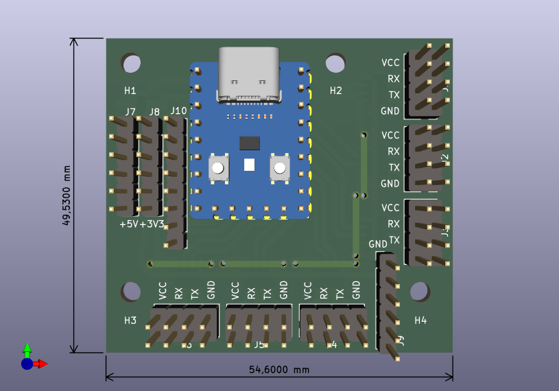
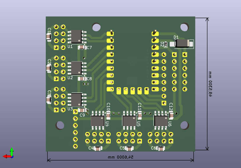
The device creates 7 /dev/ttyACM* devices when connected to a linux host.
The first 6 are linked to hardware UARTs, and /dev/ttyACM6 is used for
logging and shell.
The RP2040 only has 2 hardware UARTs. The other 4 channels use the PIOs.
Unfortunately, the pico-uart-pio driver doesn't allow changing the baud
rate at runtime. For this reason, baud rates (current-speed) for those
channels need to be set in the device tree (app.overlay).
Pin map (most of these can be changed arbitrarily):
| pin | function |
|---|---|
| P0 | Tx0 |
| P1 | Rx0 |
| P2 | Tx1 |
| P3 | Rx1 |
| P4 | Tx2 |
| P5 | Rx2 |
| P6 | Tx3 |
| P7 | Rx3 |
| P8 | Tx4 |
| P9 | Rx4 |
| P10 | Tx5 |
| P11 | Rx5 |
. ~/zephyrproject/.venv/bin/activate
. ~/zephyrproject/zephyr/zephyr-env.sh
west build

# enter bootloader: press BOOT button, press & release RESET, release BOOT
west flashsudo tee /etc/udev/rules.d/99-multicdc.rules > /dev/null << "EOF"
SUBSYSTEM=="tty", ENV{ID_VENDOR_ID}=="2fe3", ENV{ID_MODEL_ID}=="6cdc", ENV{ID_USB_INTERFACE_NUM}=="00", SYMLINK+="tty-mcdc0ch0"
SUBSYSTEM=="tty", ENV{ID_VENDOR_ID}=="2fe3", ENV{ID_MODEL_ID}=="6cdc", ENV{ID_USB_INTERFACE_NUM}=="02", SYMLINK+="tty-mcdc0ch1"
SUBSYSTEM=="tty", ENV{ID_VENDOR_ID}=="2fe3", ENV{ID_MODEL_ID}=="6cdc", ENV{ID_USB_INTERFACE_NUM}=="04", SYMLINK+="tty-mcdc0ch2"
SUBSYSTEM=="tty", ENV{ID_VENDOR_ID}=="2fe3", ENV{ID_MODEL_ID}=="6cdc", ENV{ID_USB_INTERFACE_NUM}=="06", SYMLINK+="tty-mcdc0ch3"
SUBSYSTEM=="tty", ENV{ID_VENDOR_ID}=="2fe3", ENV{ID_MODEL_ID}=="6cdc", ENV{ID_USB_INTERFACE_NUM}=="08", SYMLINK+="tty-mcdc0ch4"
SUBSYSTEM=="tty", ENV{ID_VENDOR_ID}=="2fe3", ENV{ID_MODEL_ID}=="6cdc", ENV{ID_USB_INTERFACE_NUM}=="0a", SYMLINK+="tty-mcdc0ch5"
SUBSYSTEM=="tty", ENV{ID_VENDOR_ID}=="2fe3", ENV{ID_MODEL_ID}=="6cdc", ENV{ID_USB_INTERFACE_NUM}=="0c", SYMLINK+="tty-mcdc0shell"
EOF
sudo udevadm control --reload-rules
sudo udevadm trigger| Qty | Value | Footprint | References |
|---|---|---|---|
| 8 | Conn_01x01 | Connector_Wire:SolderWire-0.25sqmm_1x01_D0.65mm_OD1.7mm_Relief | J2, J3, J4, J5, J6, J7, J8, J9 |
| 5 | 100 | Resistor_SMD:R_0805_2012Metric_Pad1.20x1.40mm_HandSolder | R1, R2, R3, R4, R5 |
| 5 | 100k | Resistor_SMD:R_0805_2012Metric_Pad1.20x1.40mm_HandSolder | R6, R7, R8, R9, R10 |
| 5 | AO3400A | Package_TO_SOT_SMD:SOT-23 | Q1, Q2, Q3, Q4, Q5 |
| 4 | MountingHole | MountingHole:MountingHole_3.2mm_M3 | H1, H2, H3, H4 |
| 1 | 0ZCF0150FF2C | Fuse:Fuse_2920_7451Metric_Pad2.10x5.45mm_HandSolder | F1 |
| 1 | 0ZCJ0025AF2E | Fuse:Fuse_1206_3216Metric_Pad1.42x1.75mm_HandSolder | F2 |
| 1 | 100n / 50V | Capacitor_SMD:C_1206_3216Metric_Pad1.33x1.80mm_HandSolder | C1 |
| 1 | 1k | Resistor_SMD:R_0805_2012Metric_Pad1.20x1.40mm_HandSolder | R11 |
| 1 | 4k7 | Resistor_SMD:R_0805_2012Metric_Pad1.20x1.40mm_HandSolder | R12 |
| 1 | EGF477M1VG16RRTHP-R | Capacitor_THT:CP_Radial_D10.0mm_P5.00mm | C2 |
| 1 | P6SMBJ24A | Diode_SMD:D_SMB_Handsoldering | D1 |
| 1 | Screw_Terminal_01x06 | ondra:TerminalBlock_Xinya_XY301VA-5.00-6P_1x06_P5.00mm_Horizontal | J10 |
| 1 | TBG-5-KB-3P/GN | ondra:TBG-5-KB-3P_1x03_P5.08mm_Horizontal | J1 |
| 1 | soldered wires | Connector_Wire:SolderWire-0.25sqmm_1x04_P4.2mm_D0.65mm_OD1.7mm_Relief | J11 |
ondras12345/multicdc
RP2040-based 6-channel USB to UART converter with Zephyr RTOS

ondras12345/CNC
My CNC 1610 and Stepcraft model 600 configuration and CNC-related notes

ondras12345/pm-sensor
SPS30-based PM2.5 particulate matter sensor with RS485


sq9nje/matrix_antenna_switch
A 2x6 matrix antenna switch for HF HAM radio

ByTechLab/RF---Mostly-3D-Printed-Discone-Antenna--0.08-1-GHz-
Mostly 3D printed discone antenna for Software Definied Radio.

ondras12345/vetrnik
Electronics for heating water with power from a 2 kW wind turbine


It measures 116 × 30 mm and has 2 copper layers, 1.6 mm thick.
37 parts, built around the AO3400A, 0ZCF0150FF2C, 0ZCJ0025AF2E and P6SMBJ24A. The full list of its parts is on this page, with links to each part's symbol and footprint where PCBKit's library has them.
From the ondras12345/multicdc repository on GitHub, at the commit this page was made from: the board is hardware/multicdc-LEDs/multicdc-LEDs.kicad_pcb and its schematic hardware/multicdc-LEDs/multicdc-LEDs.kicad_sch. PCBKit opens the board in the browser, with nothing to install.
Its repository publishes it under the MIT licence: you may reuse it on that licence's terms (keep the author's notice, and for a copyleft licence share your changes alike).