2 layers24 × 22 mm

 omzlo/fidi-hardware1
FIDI is a small development board running Adafruit's CircuitPython, featuring 6 terminal block connectors and a qwiic connector, designed for fast prototyping.
Fidi micro is an open-source printed circuit board by omzlo, from the omzlo/fidi-hardware repository on GitHub. It is a 2-layer board of 25.4 × 22 mm with 32 parts on 26 nets, routed with 329 tracks and 39 vias.
It is built around the ATSAMD21E18A-AF and GD25Q32CNIGR. Its parts include 4 capacitors, 4 resistors, 4 connectors, 3 ICs and 2 diodes. It belongs with the SAM D and SAM boards of this library.

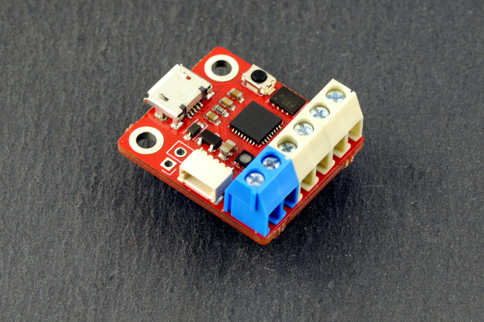
FIDI is a small development board running Adafruit's CircuitPython, featuring 6 terminal block connectors and a qwiic connector, designed for fast prototyping. It runs on the ATSAMD21 microcontroller, a 32-bit Arm Cortex M0+ clocked at 48Mhz, as found on many popular Arduino-compatible boards.
For more info, see https://www.omzlo.com/fidi
This design borrows largely from SERPENTE, by Arturo182 (https://github.com/arturo182/serpente_hw).
| Qty | Value | Footprint | References |
|---|---|---|---|
| 9 | TP_SWDIO | TestPoint:TestPoint_Pad_D1.0mm | TP1, TP2, TP4, TP7, TP8, TP9, TP10, TP11, TP12 |
| 2 | 150R | Resistor_SMD:R_0603_1608Metric | R2, R3 |
| 2 | 1uF | Capacitor_SMD:C_0603_1608Metric | C1, C4 |
| 2 | MountingHole_Pad | MountingHole:MountingHole_2.7mm_M2.5_DIN965_Pad | H1, H2 |
| 1 | 0.1uF | Capacitor_SMD:C_0603_1608Metric | C2 |
| 1 | 10uF | Capacitor_SMD:C_0805_2012Metric | C3 |
| 1 | 1K | Resistor_SMD:R_0603_1608Metric | R4 |
| 1 | 360R | Resistor_SMD:R_0603_1608Metric | R1 |
| 1 | 500mA | Diode_SMD:D_SOD-323_HandSoldering | D2 |
| 1 | ATSAMD21E18A | Package_DFN_QFN:QFN-32-1EP_5x5mm_P0.5mm_EP3.6x3.6mm | U3 |
| 1 | Conn_01x02 | Connector_PinHeader_2.54mm:PinHeader_1x02_P2.54mm_Vertical | J4 |
| 1 | Conn_01x04 | Connector_JST:JST_SH_SM04B-SRSS-TB_1x04-1MP_P1.00mm_Horizontal | J2 |
| 1 | Conn_01x06 | TerminalBlock_4Ucon:TerminalBlock_4Ucon_1x06_P3.50mm_Horizontal | J3 |
| 1 | GD25Q32CNIGR | Package_SON_Extra:USON-8_3x4mm_P0.8mm | U1 |
| 1 | LED_ARGB | LED_SMD:LED_Cree-PLCC4_2x2mm_CW | D1 |
| 1 | MCP1700-3302E_SOT23 | Package_TO_SOT_SMD:SOT-23 | U2 |
| 1 | SW_RESET | Button_Switch_SMD:SW_SPST_B3U-1000P | SW1 |
| 1 | TP_GND | TestPoint:TestPoint_Pad_D1.0mm | TP6 |
| 1 | TP_SWCLK | TestPoint:TestPoint_Pad_D1.0mm | TP3 |
| 1 | TP_VDD | TestPoint:TestPoint_Pad_D1.0mm | TP5 |
| 1 | USB_B_Micro | Connector_USB:USB_Micro-B_LCSC_C40951 | J1 |


HexSense-MIT/HS_ESP32_CAM_module
A custom designed USB camera module, with ESP32-S3R8 + OV2640. This will be used for the HexSenseCAM payload.


OpenSiPM/sipm-bias-control
Single channel silicon photomultipliers for high-speed fluorescence imaging

upbeatcarri/eclair
Pocket device for taking quick notes, acting as a USB keyboard for PC sync etc., with custom apps samd21, tinygo

M0LTE/pi-transceiver
An attempt to build a complete ham radio transceiver around a Raspberry Pi

gregdavill/cap-sense-flex
A prototype of a flex measuring sensor. Based off: https://dl.acm.org/doi/10.1145/3313831.3376269
It measures 25.4 × 22 mm and has 2 copper layers, 1.6 mm thick.
32 parts, built around the ATSAMD21E18A-AF and GD25Q32CNIGR. The full list of its parts is on this page, with links to each part's symbol and footprint where PCBKit's library has them.
From the omzlo/fidi-hardware repository on GitHub, at the commit this page was made from: the board is fidi-micro.kicad_pcb. PCBKit opens the board in the browser, with nothing to install.
Its repository states no licence, so its author keeps all rights: ask omzlo before reusing the design.