
2 layers65 × 56 mm
RPi Hat
omc8db/DigitalVoice
An open source codec2 based handheld digital radio for VHF/UHF amateur bands
76 parts1Apache-2.0

 omc8db/DigitalVoice1
An open source codec2 based handheld digital radio for VHF/UHF amateur bands
PWRBRD is an open-source printed circuit board by omc8db, from the omc8db/DigitalVoice repository on GitHub, published under the Apache-2.0 licence. It is a 2-layer board of 90 × 39.1 mm with 61 parts on 58 nets, routed with 397 tracks and 20 vias.
It is built around the LM393. Its parts include 24 resistors, 15 capacitors, 7 diodes, 5 ICs and 3 connectors.
% RPi B+ Hat
This is a project template for a Raspberry Pi B+ Hat.
This base project includes a PCB edge defined according to this specification. Both a thru-hole and a surface mount connector are provided, along with a different PCB edge for each. Just keep the PCB edge and connector type that you're using for your design and delete the others.
The component footprints used in this template are here.
The board outline looks like this:
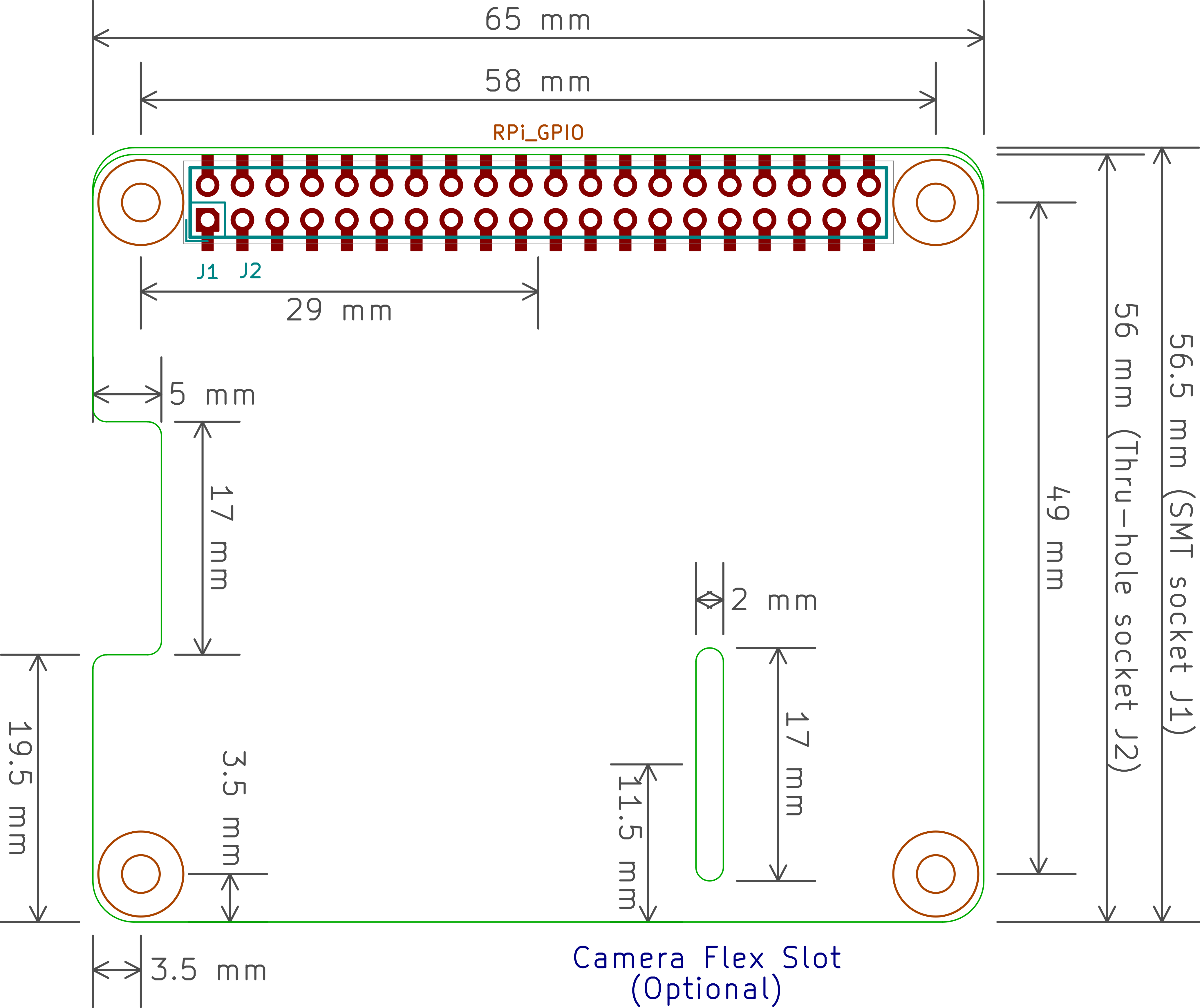
To use the Raspberry Pi Hat template with the through-hole connector, do the following:
To use the Raspberry Pi Hat template with the SMD connector, do the following:
(c)2015 XESS Corp.
| Qty | Value | Footprint | References |
|---|---|---|---|
| 14 | R | Resistors_SMD:R_0603 | R1, R2, R3, R5, R6, R7, R8, R9, R10, R11, R12, R13, R14, R18 |
| 6 | 22uF | Capacitors_SMD:CP_Elec_5x5.3 | C8, C9, C10, C12, C13, C15 |
| 5 | C | Capacitors_SMD:C_0603 | C1, C3, C4, C5, C6 |
| 3 | LED | LEDs:LED_0603 | D2, D3, D4 |
| 2 | 10uF | Capacitors_SMD:C_0603 | C7, C14 |
| 2 | 1K | Resistors_SMD:R_0603 | R23, R24 |
| 1 | 100m | Resistors_SMD:R_0603 | R20 |
| 1 | 10M | Resistors_SMD:R_0603 | R17 |
| 1 | 10k | Resistors_SMD:R_0603 | R19 |
| 1 | 1M | Resistors_SMD:R_0603 | R16 |
| 1 | 1k | Resistors_SMD:R_0603 | R4 |
| 1 | 1uH | Resistors_SMD:R_0805 | L5 |
| 1 | 27pF | Capacitors_SMD:C_0603 | C2 |
| 1 | 2K4 | Resistors_SMD:R_0603 | R22 |
| 1 | 4.7uF | Resistors_SMD:R_0805 | L1 |
| 1 | 470 | Resistors_SMD:R_0603 | R15 |
| 1 | 4mH | Choke_Axial_ThroughHole:Choke_Horizontal_RM10mm | L9 |
| 1 | 50nF | Capacitors_SMD:C_0603 | C11 |
| 1 | 51K | Resistors_SMD:R_0603 | R21 |
| 1 | 5V | Resistors_SMD:R_0603 | D5 |
| 1 | ACT2803 | Housings_DFN_QFN:QFN-40-1EP_5x5mm_Pitch0.4mm | U1 |
| 1 | CONN_01X03 | Pin_Headers:Pin_Header_Straight_1x03_Pitch1.27mm | P2 |
| 1 | CONN_01X04 | Pin_Headers:Pin_Header_Straight_1x04 | P3 |
| 1 | D | Resistors_SMD:R_0603 | D1 |
| 1 | D_Schottky | Resistors_SMD:R_0603 | D7 |
| 1 | LED | Resistors_SMD:R_0805 | D6 |
| 1 | LM393 | SMD_Packages:SOIC-8-N | U2 |
| 1 | Q_NPN_BCE | TO_SOT_Packages_SMD:SOT-23 | Q2 |
| 1 | Q_PMOS_GDS | TO_SOT_Packages_SMD:SOT-23 | Q1 |
| 1 | SC189 | TO_SOT_Packages_SMD:SOT-23-5 | U4 |
| 1 | SW_PUSH | Buttons_Switches_ThroughHole:SW_PUSH_6mm | SW1 |
| 1 | THERMISTOR | Discret:R1 | TH1 |
| 1 | TS30012 | Housings_DFN_QFN:QFN-16-1EP_3x3mm_Pitch0.5mm | U3 |
| 1 | USB_B | Connect:USB_Micro-B | P1 |
| 1 | ZXSC420 | TO_SOT_Packages_SMD:SOT-23-6 | U5 |
It measures 90 × 39.1 mm and has 2 copper layers, 1.6 mm thick.
61 parts, built around the LM393. The full list of its parts is on this page, with links to each part's symbol and footprint where PCBKit's library has them.
From the omc8db/DigitalVoice repository on GitHub, at the commit this page was made from: the board is hardware/PWRBRD/PWRBRD.kicad_pcb. PCBKit opens the board in the browser, with nothing to install.
Its repository publishes it under the Apache-2.0 licence: you may reuse it on that licence's terms (keep the author's notice, and for a copyleft licence share your changes alike).
omc8db/DigitalVoice
An open source codec2 based handheld digital radio for VHF/UHF amateur bands

omc8db/DigitalVoice
An open source codec2 based handheld digital radio for VHF/UHF amateur bands

omc8db/DigitalVoice
An open source codec2 based handheld digital radio for VHF/UHF amateur bands

omc8db/DigitalVoice
An open source codec2 based handheld digital radio for VHF/UHF amateur bands


schlae/snark-barker-mca
A Sound Blaster compatible sound card for Micro Channel bus computers

michaelruppe/FSAE
Projects for Formula SAE Electric Vehicle competition (Australia 2019/2020)

AllYarnsAreBeautiful/ayab-hardware
Contains the schematics and layouts for the AYAB Arduino shield

17o2/bluetooth-minidisc
Adding built-in bluetooth connectivity to a 20-year-old Mindisc player

bluepylons/USB-C-3-way-splitter
A splitter board (for making a cable splitter) for turning a 5V 3A USB power source to 3 5V 1A USB sources