Skip to the content
2 layers52 × 12 mmRF BW Filter, the printed circuit board in 3D

An open source codec2 based handheld digital radio for VHF/UHF amateur bands

Size
52 × 12 mm
Copper layers
2
Thickness
1.6 mm
Parts
7
Nets
4
Pads
20
Tracks, vias
81, 31
Pours
2
Routed
Yes
KiCad
KiCad 4
Created
12 Oct 2016
Updated
8 May 2017

Overview

RF BW Filter is an open-source printed circuit board by omc8db, from the omc8db/DigitalVoice repository on GitHub, published under the Apache-2.0 licence. It is a 2-layer board of 52 × 12 mm with 7 parts on 4 nets, routed with 81 tracks and 31 vias.

Its parts include 3 capacitors, 2 ICs and 2 inductors. It belongs with the radio and wireless boards of this library.

README

hardware/PiHat_Final/README.md

% RPi B+ Hat

Raspberry Pi B+ Hat

Expansion Board

This is a project template for a Raspberry Pi B+ Hat.

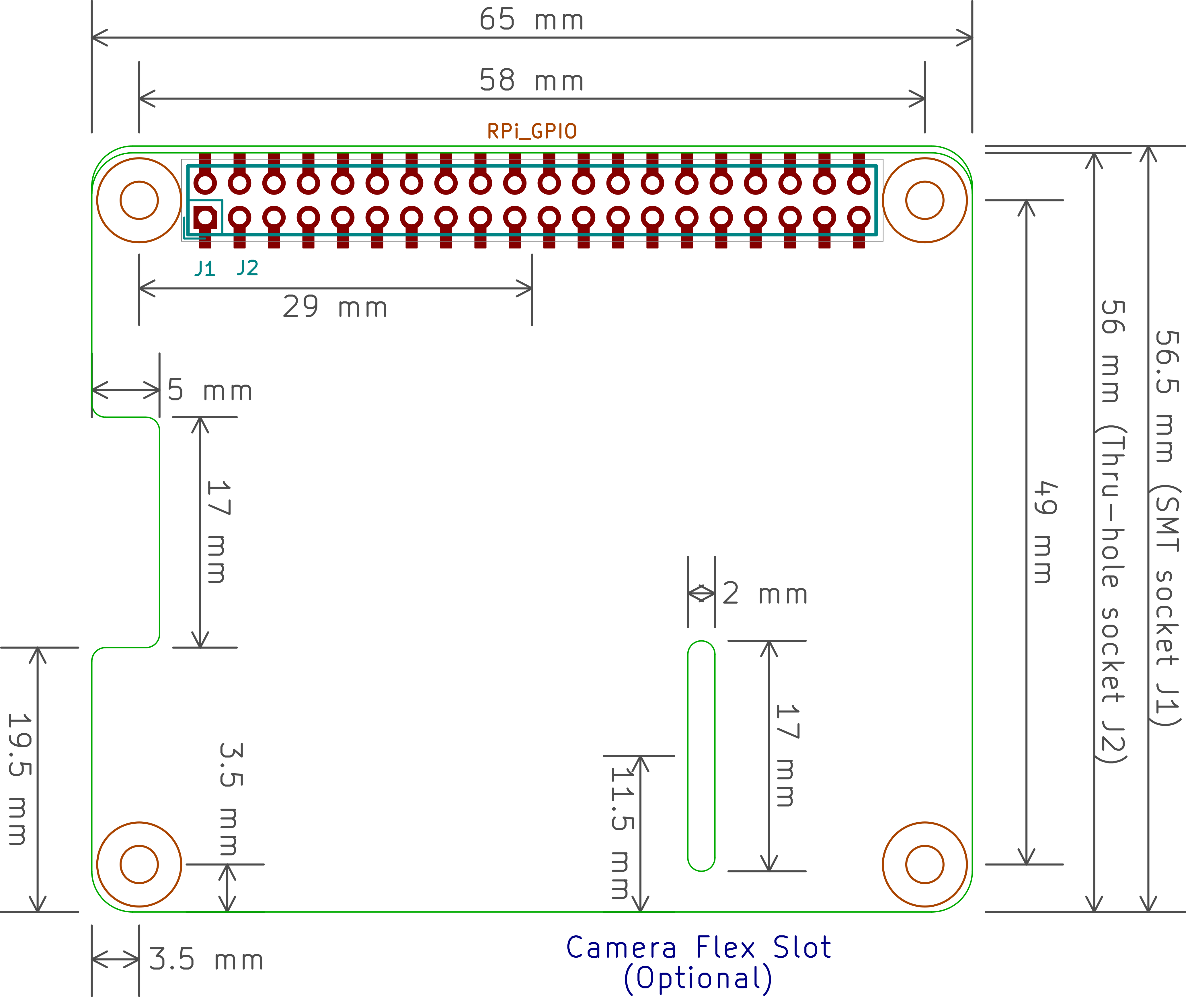
This base project includes a PCB edge defined according to this specification. Both a thru-hole and a surface mount connector are provided, along with a different PCB edge for each. Just keep the PCB edge and connector type that you're using for your design and delete the others.

The component footprints used in this template are here.

The board outline looks like this:

Using the Template

To use the Raspberry Pi Hat template with the through-hole connector, do the following:

  1. Open the schematic. Remove the SMD connector, J1.
  2. Generate the schematic netlist.
  3. Generate the .cmp file. (The J2 connector will be the only component in it.)
  4. Open the PCB. Hover your mouse over the connector and hit e to edit it. Select the J1 SMD connector. In the Move and Place section of the Footprint Properties window, select the Free radio button. Then click OK. The SMD connector should now be unlocked so it can be removed.
  5. Read in the netlist from the schematic. In the Extra Footprints section of the Netlist dialog window, select the Delete radio button. Then click Read Current Netlist. The J1 SMD connector should disappear. Then click Close.
  6. Finally, delete the upper two arcs and the edge of the board outline.

To use the Raspberry Pi Hat template with the SMD connector, do the following:

  1. Open the schematic. Remove the through-hole connector, J2.
  2. Generate the schematic netlist.
  3. Generate the .cmp file. (The J1 connector will be the only component in it.)
  4. Open the PCB. Hover your mouse over the connector and hit e to edit it. Select the J2 through-hole connector. In the Move and Place section of the Footprint Properties window, select the Free radio button. Then click OK. The through-hole connector should now be unlocked so it can be removed.
  5. Read in the netlist from the schematic. In the Extra Footprints section of the Netlist dialog window, select the Delete radio button. Then click Read Current Netlist. The J2 through-hole connector should disappear. Then click Close.
  6. Finally, delete the lower two arcs and the edge of the board outline.

(c)2015 XESS Corp.

Parts

7
QtyValueFootprintReferences
213uHResistors_SMD:R_0805L1, L2
22000pFCapacitors_SMD:C_0805C1, C3
2SMA_Edge_MountRF BW Filter:SMA_Edge_MountU1, U2
13600pFCapacitors_SMD:C_0805C2

More from omc8db/DigitalVoice

4
  • 2 layers65 × 56 mmRPi Hat, the printed circuit board in 3D

    RPi Hat

    omc8db/DigitalVoice

    An open source codec2 based handheld digital radio for VHF/UHF amateur bands

    76 parts1Apache-2.0
  • 2 layers90 × 39.1 mmPWRBRD, the printed circuit board in 3D

    PWRBRD

    omc8db/DigitalVoice

    An open source codec2 based handheld digital radio for VHF/UHF amateur bands

    61 parts1Apache-2.0
  • 2 layers85 × 56 mmPihat, the printed circuit board in 3D

    Pihat

    omc8db/DigitalVoice

    An open source codec2 based handheld digital radio for VHF/UHF amateur bands

    49 parts1Apache-2.0
  • 2 layers65 × 56 mmRPi Hat, the printed circuit board in 3D

    RPi Hat

    omc8db/DigitalVoice

    An open source codec2 based handheld digital radio for VHF/UHF amateur bands

    46 parts1Apache-2.0

Similar boards

  • 2 layersEncoder, the printed circuit board in 3D

    Encoder

    byrantech/laptop

    anyon_e, a highly integrated, high end, open source laptop. Attempt the impossible.

    7 parts4.3kMIT
  • 2 layers40 × 20 mmSensor smd, the printed circuit board in 3D

    Sensor smd

    scottbez1/splitflap

    DIY split-flap display

    7 parts4.2k
  • 2 layers19.8 × 30 mmZ limit, the printed circuit board in 3D

    Z limit

    opulo-inc/lumenpnp

    The LumenPnP is an open source pick and place machine.

    7 parts3.7k
  • 2 layers35.6 × 58.2 mmDisplay Carrier, the printed circuit board in 3D

    Display Carrier

    AxxAxx/AxxSolder

    STM32 Based soldering station for JBC cartridges, 9-24 VDC and USB-PD power

    7 parts1.7kGPL-3.0
  • 2 layers20.3 × 16.3 mmMap MPX, the printed circuit board in 3D

    Map MPX

    rusefi/rusefi

    rusefi - GPL internal combustion engine control unit

    7 parts1.2k
  • 2 layers26 × 44 mmCompact carrier board, the printed circuit board in 3D

    Compact carrier board

    jamro/tiny-engineer

    A small desktop robot that brings an AI coding assistant to life, physically acting out when it reads files, thinks, writes code, and finishes work.

    7 parts1.1k
  • 2 layers26.4 × 53.8 mmAtari pickup, the printed circuit board in 3D

    Atari pickup

    hoglet67/RGBtoHDMI

    Bare-metal Raspberry Pi project that provides pixel-perfect sampling of Retro Computer RGB/YUV video and conversion to HDMI

    7 parts1kGPL-3.0
  • 2 layersRj45 breakout, the printed circuit board in 3D

    Rj45 breakout

    rene-dev/stmbl

    AC Servo Driver for STM32F4

    7 parts990GPL-3.0

Questions

How big is the RF BW Filter PCB?

It measures 52 × 12 mm and has 2 copper layers, 1.6 mm thick.

What parts does the RF BW Filter use?

7 parts. The full list of its parts is on this page, with links to each part's symbol and footprint where PCBKit's library has them.

Where can I download the RF BW Filter KiCad files?

From the omc8db/DigitalVoice repository on GitHub, at the commit this page was made from: the board is hardware/RF BW Filter/RF BW Filter/RF BW Filter.kicad_pcb. PCBKit opens the board in the browser, with nothing to install.

Can I use the RF BW Filter design in my own project?

Its repository publishes it under the Apache-2.0 licence: you may reuse it on that licence's terms (keep the author's notice, and for a copyleft licence share your changes alike).