4 layers37.1 × 61.5 mm
MCLZ8 PCB
MicroCoreLabs/Projects
Ted Fried's MicroCore Labs Projects - FPGA CPU cores and emulators for the 8088, 8086, 8051, 6502, 68000, Z80, Risc-V, and also Typewriter and EPROM Emulator projects.
6 parts534

 olsch01/DoorKing1837-ColorDisplay
Software and Hardware solution to modernize the 8 line LCD Character display of a Doorking DKS 1837 Access Control System.
Dks1837 shield is an open-source printed circuit board by olsch01, from the olsch01/DoorKing1837-ColorDisplay repository on GitHub, published under the MIT licence. It is a 4-layer board of 39 × 82 mm with 13 parts on 26 nets, routed with 211 tracks and 7 vias.
It is built around the SN74LVC573AN, SN74HC14N and SN74LVC245AN. Its parts include 5 capacitors, 4 ICs and 2 connectors. It belongs with the lEDs and displays boards of this library.


A 4-layer "hat" that implements the Wiring Guide V1.0 circuit on a single board. J1 (underside) plugs straight onto the Olimex ESP32-P4-PC's EXT1 header and the DKS 20-way ribbon plugs into J2.
| Top | Bottom |
|---|---|
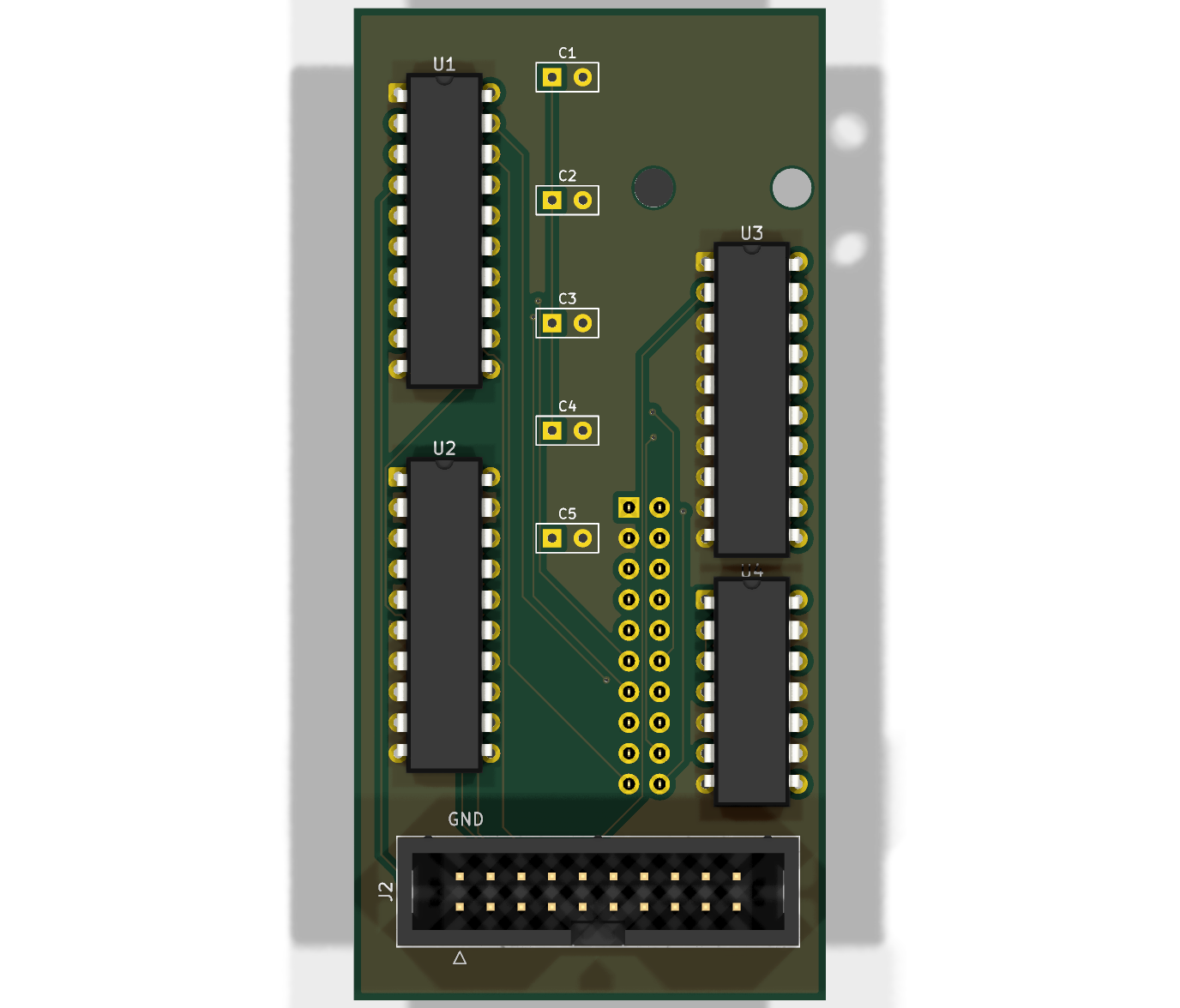 | 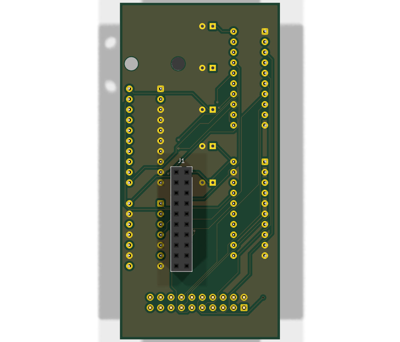 |
| Size | 39 × 82 mm |
| Layers | 4 — F.Cu signals · In1.Cu solid GND plane · In2.Cu +3.3 V plane · B.Cu signals |
| Thickness | 1.6 mm FR-4 |
| Min track / clearance | 0.15 mm (6 mil) · vias 0.3 mm drill / 0.6 mm pad |
| Finish | ENIG recommended (flat pads, better durability and shelf life than HASL) |
| DRC | 0 violations, 0 unconnected (report) |
| Mounting | Two M3 holes aligned with the Olimex board's mounting holes, plus the EXT1 header |
| Mechanical | Sits over EXT1 only and clears the Olimex's tall parts (USB-A, HDMI, UEXT) on ~10 mm standoffs; HDMI and USB-C stay accessible. Overhangs the Olimex's left edge by ~17 mm. |
All parts are through-hole and hand-solderable. See dks1837_shield_BOM.csv.
| Ref | Part | Qty |
|---|---|---|
| U1, U3 | SN74LVC573AN (DIP-20) | 2 |
| U2 | SN74LVC245AN (DIP-20) | 1 |
| U4 | SN74HC14N (DIP-14) | 1 |
| C1–C4 | 0.1 µF ceramic, 2.54 mm lead pitch | 4 |
| C5 | 10 µF, 2.54 mm lead pitch | 1 |
| J1 | 2×10 2.54 mm female header — e.g. Connectors Pro 2X10-20P (Amazon B08R8ST38L) | 1 |
| J2 | 2×10 2.54 mm straight IDC box header — e.g. uxcell 20-pin (Amazon B0107299C0) | 1 |
The LCSC numbers listed for the capacitors are unverified suggestions — check stock and ratings before ordering. The optional VEML7700 light sensor is not on this board; wire it to the Olimex UEXT connector (Wiring Guide §7).
Zip the contents of gerbers/ (copper ×4, solder mask ×2, silkscreen ×2, board outline,
drill file) and upload to any PCB fab. Select 4 layers, 1.6 mm, and the dimensions will be
detected as 39 × 82 mm. The reference boards were made by JLCPCB (5 pcs, ENIG, standard build).
J2 is wired for the reference unit's ribbon socket, whose polarizing key sits on the even-pin side. With that socket seated, each conductor lands on the pad shown below, so the J2 net assignment is mirrored across the header's long axis relative to a textbook straight-through connection (every column pair 1↔2, 3↔4, … is swapped):
| J2 pad | Ribbon conductor | Signal | J2 pad | Ribbon conductor | Signal | |
|---|---|---|---|---|---|---|
| 2 | 1 | GND (silkscreen "GND") | 1 | 2 | — (+5 V, not used) | |
| 3 | 4 | RS | 4 | 3 | — (VO) | |
| 5 | 6 | E | 6 | 5 | R/W | |
| 7 | 8 | DB1 | 8 | 7 | DB0 | |
| 9 | 10 | DB3 | 10 | 9 | DB2 | |
| 11 | 12 | DB5 | 12 | 11 | DB4 | |
| 13 | 14 | DB7 | 14 | 13 | DB6 | |
| 15–20 | 16, 15, 18, 17, 20, 19 | not connected |
Before first power-up, confirm by continuity that the J2 pad marked GND connects to DKS
ground. If your ribbon socket is keyed the standard way (pin 1 on the key side), revert the
column-pair swap described in the NOTE block of netlist.py and regenerate the
board.
netlist.py defines every component and net and is the single source of truth — there
is no separate KiCad schematic. dks1837-shield-netlist-review-v12.html
is a readable net-by-net listing generated from it.
The committed dks1837_shield.kicad_pcb is the verified, DRC-clean board. To regenerate it you need
KiCad 10 (its bundled Python provides pcbnew), Java 17+, and the
Freerouting v2.4.1 jar. Tool locations default to a
macOS install and can be overridden with KICAD_FOOTPRINT_DIR, JAVA, FREEROUTING_JAR and
KICAD_CLI.
KPY=/Applications/KiCad/KiCad.app/Contents/Frameworks/Python.framework/Versions/3.9/bin/python3.9

$KPY generate_pcb.py            # place -> autoroute (Freerouting) -> 4-layer promotion -> DRC summary
$KPY generate_fab.py            # BOM + CPL
python3 generate_review.py      # netlist review page
kicad-cli pcb export gerbers --no-protel-ext -o gerbers/ dks1837_shield.kicad_pcb
kicad-cli pcb export drill -o gerbers/ dks1837_shield.kicad_pcb
kicad-cli pcb drc --severity-error dks1837_shield.kicad_pcb
generate_pcb.py place stops after placement if you want to route by hand. Freerouting is not
deterministic, so a regenerated board will route differently from the committed one — always re-check
DRC.
| Qty | Value | Footprint | References |
|---|---|---|---|
| 4 | 0.1uF | C_THT_P2.54mm | C1, C2, C3, C4 |
| 2 | MountingHole_3.2mm_M3 | MountingHole_3.2mm_M3 | H1, H2 |
| 2 | SN74LVC573AN | DIP-20_W7.62mm | U1, U3 |
| 1 | 10uF | C_THT_P2.54mm | C5 |
| 1 | DKS_FC-20P | IDC-Header_2x10_P2.54mm_Vertical | J2 |
| 1 | EXT1_socket | PinSocket_2x10_P2.54mm_Vertical | J1 |
| 1 | SN74HC14N | DIP-14_W7.62mm | U4 |
| 1 | SN74LVC245AN | DIP-20_W7.62mm | U2 |
MicroCoreLabs/Projects
Ted Fried's MicroCore Labs Projects - FPGA CPU cores and emulators for the 8088, 8086, 8051, 6502, 68000, Z80, Risc-V, and also Typewriter and EPROM Emulator projects.

PhoenixRacing/Sensing2017
Arduino code for tach, speedometer, CVT temp, dash, etc.

Neil427/Speeduino-Hall-Trigger-Conditioner
Speeduino Hall sensor conditioner board with buffering

jeff-voight/StupidDogFocuser
As open-source electronic telescope focuser

MaximeZimmermann/OpenSpritzer-V2
OpenSpritzer v2 An Open hardware pressure ejection system for reliably delivering picolitre volumes. developed by M.J.Y. Zimmermann


paulbruneau/ssio-check
A bench tester for the Bally/Midway MCR Sound I/O family: the 90908 Sound I/O and the 90913 / 91483 / 91657 Super Sound I/O (Z80, two AY-3-8910s, and all of the game's input ports).
It measures 39 × 82 mm and has 4 copper layers, 1.6 mm thick.
13 parts, built around the SN74LVC573AN, SN74HC14N and SN74LVC245AN. The full list of its parts is on this page, with links to each part's symbol and footprint where PCBKit's library has them.
From the olsch01/DoorKing1837-ColorDisplay repository on GitHub, at the commit this page was made from: the board is hardware/pcb/dks1837_shield.kicad_pcb. PCBKit opens the board in the browser, with nothing to install.
Its repository publishes it under the MIT licence: you may reuse it on that licence's terms (keep the author's notice, and for a copyleft licence share your changes alike).