4 layers80 × 120 mm

 hiramrodriguez14/Load-UI_MCU
Load and UI MCU Hardware Design Repository.
Load UI MCU is an open-source printed circuit board by hiramrodriguez14, from the hiramrodriguez14/Load-UI_MCU repository on GitHub, published under the MIT licence. It is a 4-layer board of 85 × 90 mm with 116 parts on 110 nets, routed with 1,076 tracks and 302 vias.
It is built around the MSPM0G3519SPMR, INA229AQDGSRQ1 and TC4429CPA, with the SN74HC14N among its other parts. Its parts include 37 resistors, 27 capacitors, 22 connectors, 6 ICs and 5 diodes.


Printed Circuit Board (PCB) design for the Load Control & User Interface (Load & UI) MCU of the Horizontal Axis Wind Turbine Electronic Control Unit (ECU).
This repository contains the complete KiCad hardware design, manufacturing files, and production documentation for the embedded controller responsible for battery charging, power management, user interaction, and system monitoring.
| Resource | Link |
|---|---|
| 🎥 Project Demonstration | https://www.youtube.com/watch?v=vS5Ok38P1Jk |
| 📄 Final Project Report | https://drive.google.com/file/d/1cckKhvj7mvzCEbm3IqWp0KvrUp9g6mgg/view?usp=sharing |
| 📚 Technical Appendix | https://drive.google.com/file/d/1xu7MtcffDlpna8_BUkwEc_BfjpQJpUep/view?usp=sharing |
The Load Control & User Interface PCB serves as the primary electrical control board of the Horizontal Axis Wind Turbine Electronic Control Unit (ECU).
Designed using KiCad, this board integrates sensing, power management, user interaction, communication, and data logging into a single embedded platform. It operates alongside the Turbine MCU PCB to provide complete supervision of the wind turbine system.
The PCB was designed with debugging, manufacturability, and future expansion in mind, incorporating dedicated test points, modular circuitry, and production-ready manufacturing files.
The PCB integrates the following subsystems:
The Load Control & UI PCB serves as the electrical management hub of the complete ECU.
Primary functions include:
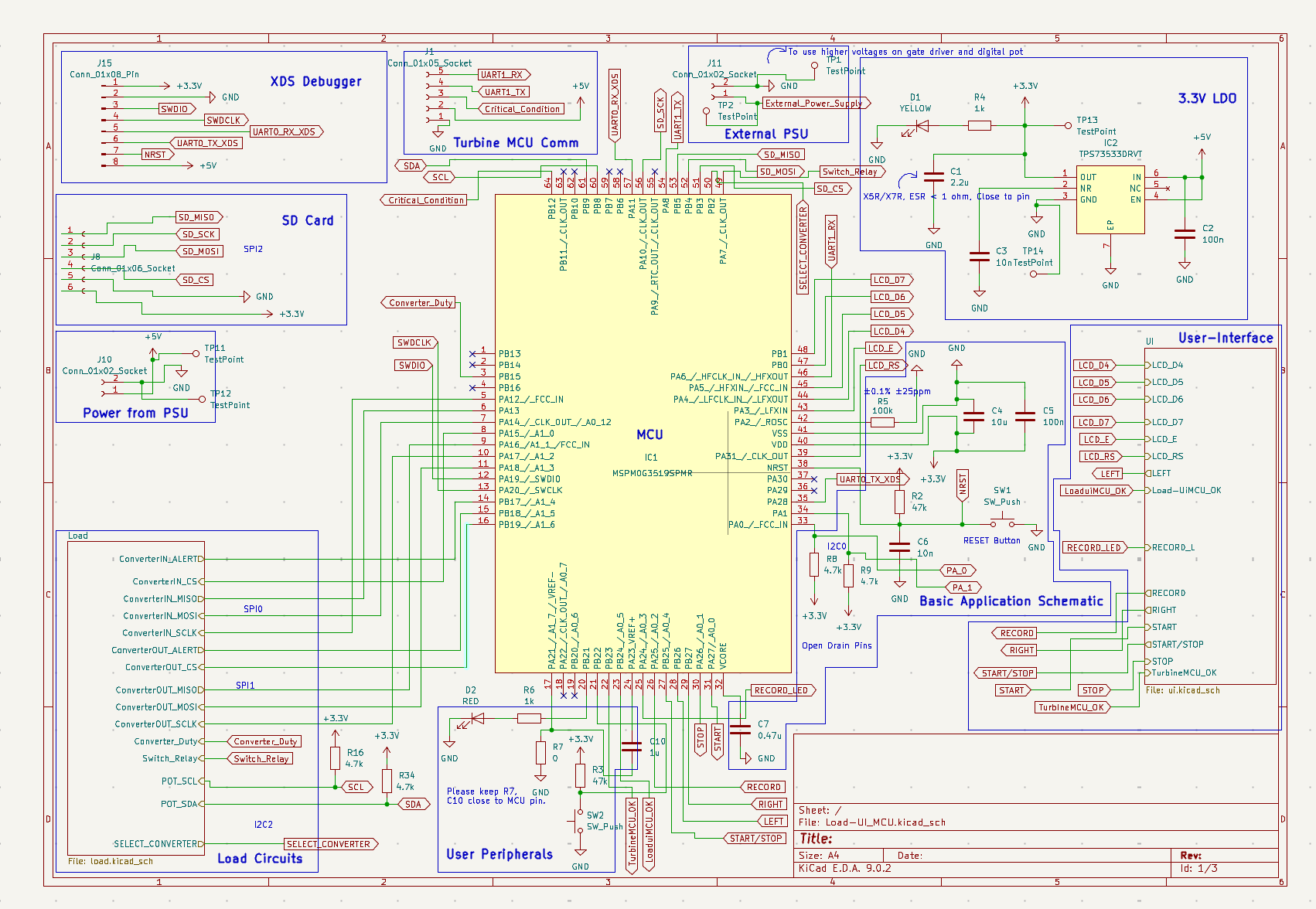
Figure 1. Load & UI MCU Architecture
The board was designed using KiCad following standard PCB design practices for embedded systems.
Design considerations include:
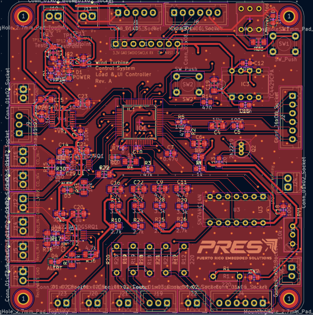
Figure 2. Top Layer PCB Layout
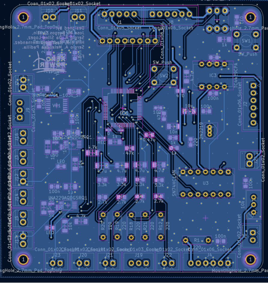
Figure 3. Bottom Layer PCB Layout
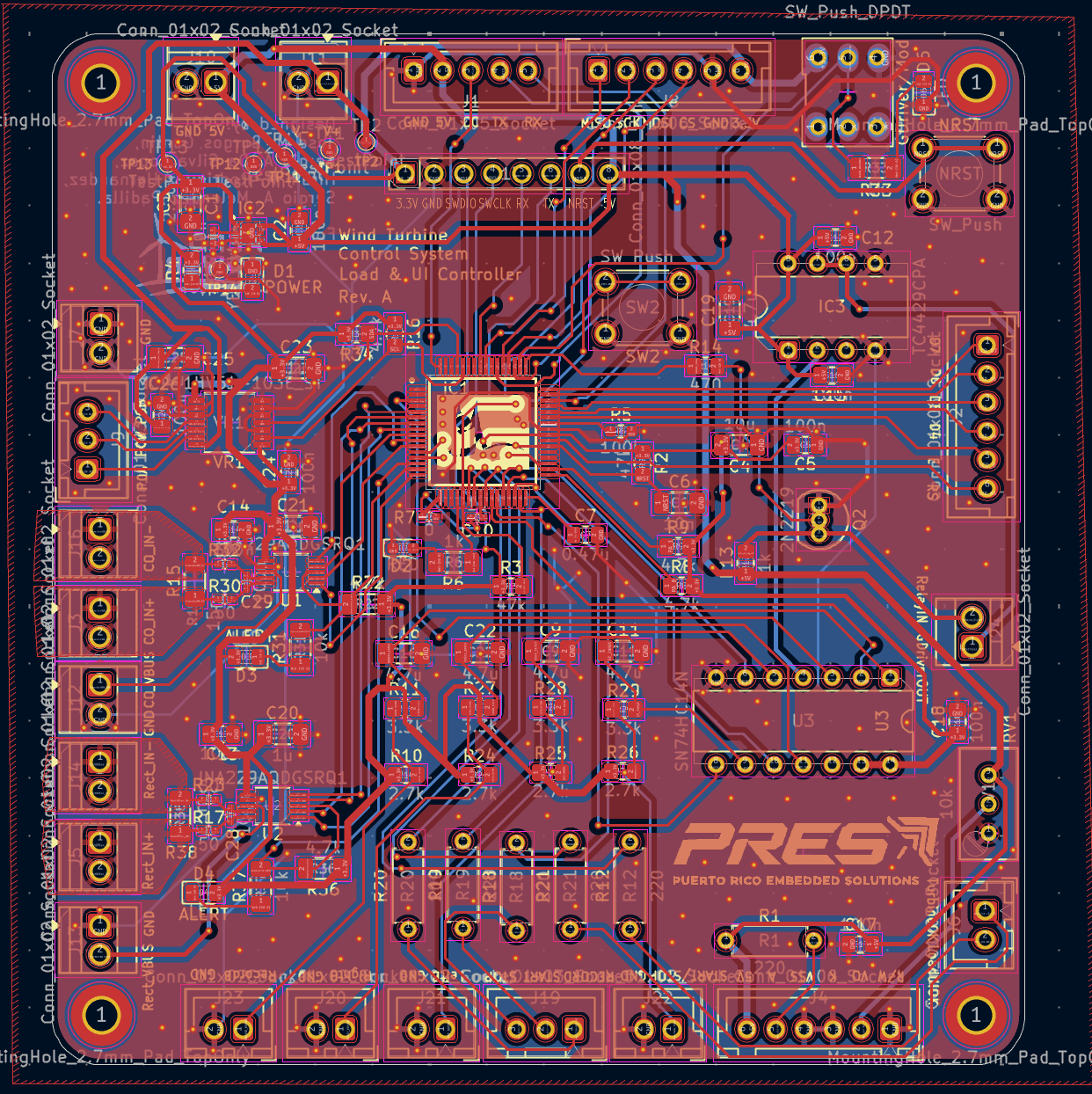
Figure 4. Combined PCB Layers
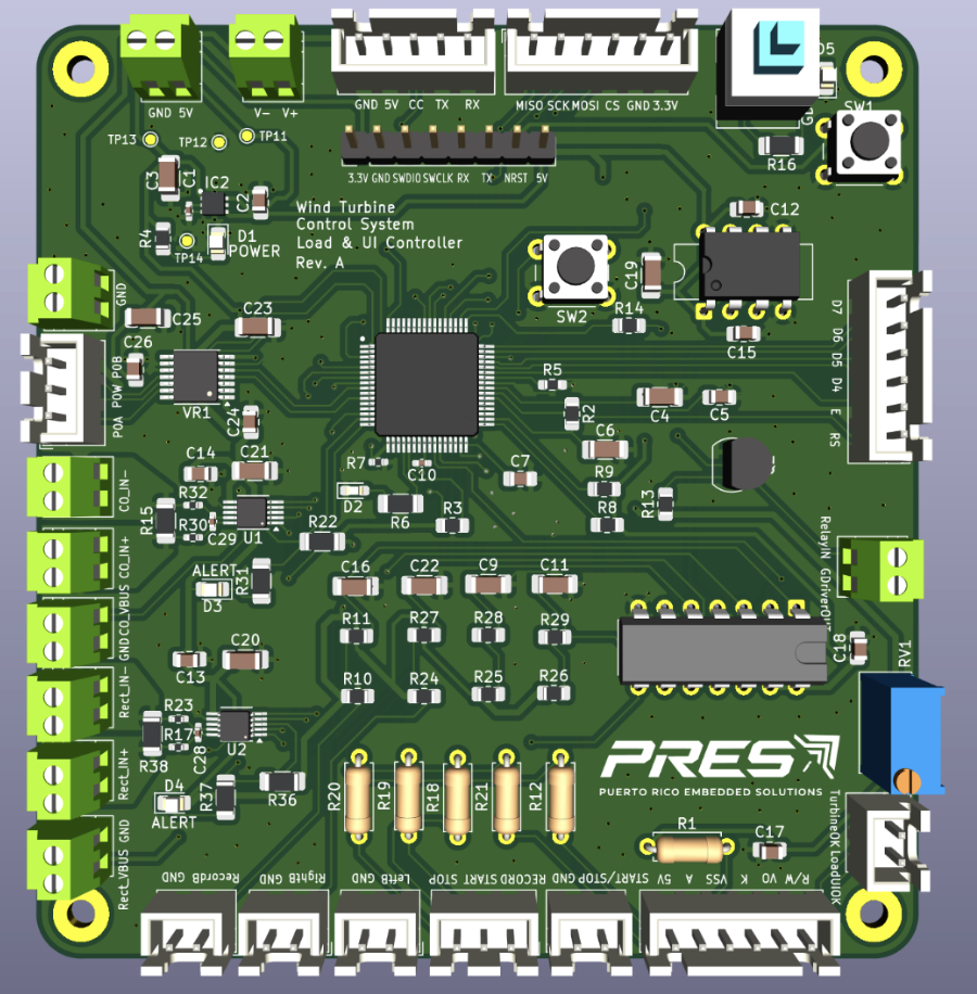
Figure 5. 3D PCB Rendering
This repository includes all files required for PCB fabrication and assembly.
Included manufacturing assets:
HAWT-LoadUI-PCB
│
├── gerbers/                    Manufacturing Gerber files
├── images/                     Documentation images
├── mylib/                      Custom KiCad component library
├── Load-UI_MCU.kicad_pcb       PCB layout
├── Load-UI_MCU.kicad_sch       Main schematic
├── Load-UI_MCU.kicad_pro       KiCad project
├── Load-UI_MCU-final.csv       Manufacturing BOM
├── Load-UI_MCU-all-pos.csv     Pick-and-Place (CPL)
├── load.kicad_sch              Power subsystem schematic
├── ui.kicad_sch                User Interface schematic
├── README.md                   Repository documentation
└── LICENSE Project license| Repository | Description |
|---|---|
| HAWT-TurbineMCU-Firmware | Turbine control firmware |
| HAWT-Load_Control_and_UI | Load Control & UI firmware |
| Turbine_MCU | Turbine MCU PCB |
Department of Electrical & Computer Engineering
University of Puerto Rico – Mayagüez
This project was developed for educational and research purposes as part of the Embedded Systems Design course at the University of Puerto Rico – Mayagüez.
| Qty | Value | Footprint | References |
|---|---|---|---|
| 10 | 100n | Capacitor_SMD:C_0805_2012Metric_Pad1.18x1.45mm_HandSolder | C2, C5, C12, C13, C14, C15, C17, C18, C24, C26 |
| 10 | Conn_01x02_Socket | TerminalBlock:TerminalBlock_Xinya_XY308-2.54-2P_1x02_P2.54mm_Horizontal | J3, J5, J7, J10, J11, J12, J13, J14, J16, J24 |
| 6 | TestPoint | TestPoint:TestPoint_Pad_D1.0mm | TP1, TP2, TP11, TP12, TP13, TP14 |
| 5 | 220 | Resistor_THT:R_Axial_DIN0207_L6.3mm_D2.5mm_P7.62mm_Horizontal | R1, R12, R18, R19, R21 |
| 5 | 4.7u | Capacitor_SMD:C_1206_3216Metric_Pad1.33x1.80mm_HandSolder | C9, C11, C16, C19, C22 |
| 5 | Conn_01x02_Socket | Connector_JST:JST_XH_B2B-XH-A_1x02_P2.50mm_Vertical | J6, J20, J21, J22, J23 |
| 4 | 1u | Capacitor_SMD:C_1206_3216Metric_Pad1.33x1.80mm_HandSolder | C20, C21, C23, C25 |
| 4 | 2.7k | Resistor_SMD:R_0805_2012Metric_Pad1.20x1.40mm_HandSolder | R10, R24, R25, R26 |
| 4 | 3.3k | Resistor_SMD:R_0805_2012Metric_Pad1.20x1.40mm_HandSolder | R11, R27, R28, R29 |
| 4 | 4.7k | Resistor_SMD:R_0805_2012Metric_Pad1.20x1.40mm_HandSolder | R8, R9, R16, R34 |
| 4 | 50 | Resistor_SMD:R_0402_1005Metric_Pad0.72x0.64mm_HandSolder | R17, R23, R30, R32 |
| 3 | Conn_01x06_Socket | Connector_JST:JST_XH_B6B-XH-A_1x06_P2.50mm_Vertical | J2, J4, J8 |
| 3 | LED | LED_SMD:LED_0805_2012Metric_Pad1.15x1.40mm_HandSolder | D3, D4, D6 |
| 3 | LOGO | LOGO | G***, G***, G*** |
| 2 | 100n | Capacitor_SMD:C_0402_1005Metric_Pad0.74x0.62mm_HandSolder | C28, C29 |
| 2 | 10k | Resistor_SMD:R_1206_3216Metric_Pad1.30x1.75mm_HandSolder | R31, R37 |
| 2 | 15m | Resistor_SMD:R_1206_3216Metric_Pad1.30x1.75mm_HandSolder | R15, R38 |
| 2 | 1k | Resistor_SMD:R_0805_2012Metric_Pad1.20x1.40mm_HandSolder | R4, R13 |
| 2 | 1k | Resistor_SMD:R_1206_3216Metric_Pad1.30x1.75mm_HandSolder | R6, R33 |
| 2 | 4.7k | Resistor_SMD:R_1206_3216Metric_Pad1.30x1.75mm_HandSolder | R22, R36 |
| 2 | 47k | Resistor_SMD:R_0805_2012Metric_Pad1.20x1.40mm_HandSolder | R2, R3 |
| 2 | Conn_01x03_Socket | Connector_JST:JST_XH_B3B-XH-A_1x03_P2.50mm_Vertical | J9, J19 |
| 2 | INA229AQDGSRQ1 | Package_SO:VSSOP-10_3x3mm_P0.5mm | U1, U2 |
| 2 | SW_Push | Button_Switch_THT:SW_PUSH_6mm | NRST, SW2 |
| 1 | 0 | Resistor_SMD:R_0402_1005Metric_Pad0.72x0.64mm_HandSolder | R7 |
| 1 | 0.47u | Capacitor_SMD:C_0805_2012Metric_Pad1.18x1.45mm_HandSolder | C7 |
| 1 | 100 | Resistor_THT:R_Axial_DIN0207_L6.3mm_D2.5mm_P7.62mm_Horizontal | R20 |
| 1 | 100k | Resistor_SMD:R_0603_1608Metric_Pad0.98x0.95mm_HandSolder | R5 |
| 1 | 10k | Potentiometer_THT:Potentiometer_Bourns_3296W_Vertical | RV1 |
| 1 | 10n | Capacitor_SMD:C_0402_1005Metric_Pad0.74x0.62mm_HandSolder | C3 |
| 1 | 10n | Capacitor_SMD:C_1206_3216Metric_Pad1.33x1.80mm_HandSolder | C6 |
| 1 | 10u | Capacitor_SMD:C_1206_3216Metric_Pad1.33x1.80mm_HandSolder | C4 |
| 1 | 1u | Capacitor_SMD:C_0402_1005Metric_Pad0.74x0.62mm_HandSolder | C10 |
| 1 | 2.2u | Capacitor_SMD:C_1206_3216Metric_Pad1.33x1.80mm_HandSolder | C1 |
| 1 | 2N2219 | Package_TO_SOT_THT:TO-92_Inline | Q2 |
| 1 | 470 | Resistor_SMD:R_0805_2012Metric_Pad1.20x1.40mm_HandSolder | R14 |
| 1 | Conn_01x05_Socket | Connector_JST:JST_XH_B5B-XH-A_1x05_P2.50mm_Vertical | J1 |
| 1 | Conn_01x08_Pin | Connector_PinHeader_2.54mm:PinHeader_1x08_P2.54mm_Vertical | J15 |
| 1 | MCP41HV51-103E_ST | Package_SO:TSSOP-14_4.4x5mm_P0.65mm | VR1 |
| 1 | MSPM0G3519SPMR | MSPM0SPMR:QFP50P1200X1200X160-64N | IC1 |
| 1 | RED | LED_SMD:LED_0603_1608Metric_Pad1.05x0.95mm_HandSolder | D2 |
| 1 | SN74HC14N | Package_DIP:CERDIP-14_W7.62mm_SideBrazed | U3 |
| 1 | SW_Push_DPDT | Latch_PB:SW_DPDT_XLX | SW4 |
| 1 | TC4429CPA | Package_DIP:CERDIP-8_W7.62mm_SideBrazed | IC3 |
| 1 | TPS73533DRVT | TPS73533DRVT:SON65P200X200X80-7N | IC2 |
| 1 | YELLOW | LED_SMD:LED_0805_2012Metric_Pad1.15x1.40mm_HandSolder | D1 |
The 112 most common of 116 parts.

GGoodacre/WindChargeController-Capstone2024
Solar Charge Controller for BEng Capstone 2024

PhoenixRacing/Sensing2017
Arduino code for tach, speedometer, CVT temp, dash, etc.

Neil427/Speeduino-Hall-Trigger-Conditioner
Speeduino Hall sensor conditioner board with buffering

jeff-voight/StupidDogFocuser
As open-source electronic telescope focuser

MaximeZimmermann/OpenSpritzer-V2
OpenSpritzer v2 An Open hardware pressure ejection system for reliably delivering picolitre volumes. developed by M.J.Y. Zimmermann


olsch01/DoorKing1837-ColorDisplay
Software and Hardware solution to modernize the 8 line LCD Character display of a Doorking DKS 1837 Access Control System.
It measures 85 × 90 mm and has 4 copper layers, 1.6 mm thick.
116 parts, built around the MSPM0G3519SPMR, INA229AQDGSRQ1, TC4429CPA and SN74HC14N. The full list of its parts is on this page, with links to each part's symbol and footprint where PCBKit's library has them.
From the hiramrodriguez14/Load-UI_MCU repository on GitHub, at the commit this page was made from: the board is Load-UI_MCU.kicad_pcb and its schematic Load-UI_MCU.kicad_sch. PCBKit opens the board in the browser, with nothing to install.
Its repository publishes it under the MIT licence: you may reuse it on that licence's terms (keep the author's notice, and for a copyleft licence share your changes alike).