2 layers

 oliverpaddock/OpenMic
An open source audio interface
Power v2 is an open-source printed circuit board by oliverpaddock, from the oliverpaddock/OpenMic repository on GitHub, published under the CERN-OHL-S-2.0 licence. It is a 2-layer board of 15.2 × 71.1 mm with 52 parts on 39 nets, routed with 325 tracks and 105 vias.
It is built around the TPS2116DRL, TUSB3210PM and CSD87501L. Its parts include 22 capacitors, 11 resistors, 6 connectors, 4 diodes and 3 ICs.


OpenMic is an open-source, 2-in, 2-out, usb-c audio interface.
Open source audio/music hardware is not scarce, but general-purpose open source audio interfaces for musicians are essentially non-existent. OpenMic brings repairability, transparency, and education to an overlooked corner of music hardware.
You own your hardware. All schematics, firmware, and design files are publicly accessible so you can repair it, modify it, and understand it.
If you aren't familiar with audio interfaces like the Focusrite Scarlett 2i2 or the Universal Audio Apollo Twin, they basically take analog audio - from a microphone, a guitar, a synth, etc. - and convert it into digital audio your computer can use in a DAW like Ableton, Logic, or Audacity. They also convert digital audio from your computer back into analog audio that you can hear through speakers or headphones. Interfaces also typically provide some sort of amplification or volume control on the inputs and outputs.
This is exactly what OpenMic does. Two inputs that can take microphone/line/instrument level signals, outputs for your speakers, and a headphone jack. Plus a few other features like phantom power that are listed in more detail in the Features section.
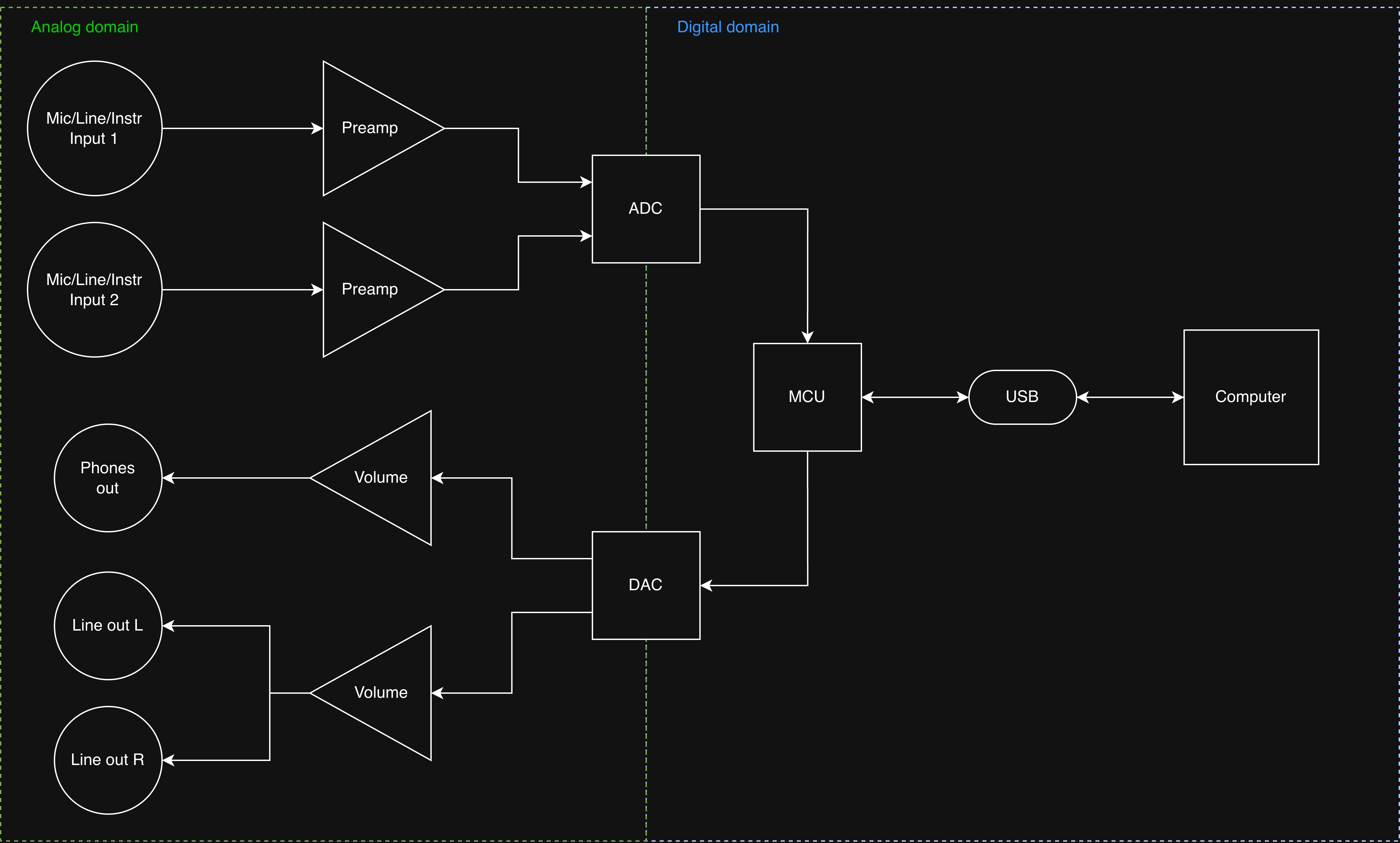 System block diagram
OpenMic is currently in the prototyping stage. The circuit has been designed and simulated, and individual systems are being built and tested. View the schematics to see the current circuit design.
Progress will be posted on the OpenMic blog as prototyping continues.
If you want to view/edit KiCAD files, make sure to add the part libraries located in /hardware/libs to your project or globally in your KiCAD instance.


THAT Corporation
Neutrik
| Qty | Value | Footprint | References |
|---|---|---|---|
| 8 | 10nF | Capacitor_SMD:C_0805_2012Metric_Pad1.18x1.45mm_HandSolder | C2, C3, C4, C5, C14, C15, C16, C17 |
| 4 | 10k | Resistor_SMD:R_0805_2012Metric_Pad1.20x1.40mm_HandSolder | R3, R7, R8, R12 |
| 4 | 330pF | Capacitor_SMD:C_0805_2012Metric_Pad1.18x1.45mm_HandSolder | C6, C7, C18, C19 |
| 4 | R | LED_SMD:LED_0805_2012Metric_Pad1.15x1.40mm_HandSolder | D1, D3, D4, D5 |
| 3 | 22uF | Capacitor_SMD:C_0805_2012Metric_Pad1.18x1.45mm_HandSolder | C10, C11, C22 |
| 3 | 4.7uF | Capacitor_SMD:C_0805_2012Metric_Pad1.18x1.45mm_HandSolder | C1, C9, C13 |
| 2 | 10uF | Capacitor_SMD:C_0805_2012Metric_Pad1.18x1.45mm_HandSolder | C8, C12 |
| 2 | 1uF | Capacitor_SMD:C_0805_2012Metric_Pad1.18x1.45mm_HandSolder | C20, C21 |
| 2 | 4.7k | Resistor_SMD:R_0805_2012Metric_Pad1.20x1.40mm_HandSolder | R6, R11 |
| 2 | D_PIN | Connector_PinHeader_1.00mm:PinHeader_1x02_P1.00mm_Vertical | J3, J5 |
| 1 | 180k | Resistor_SMD:R_0805_2012Metric_Pad1.20x1.40mm_HandSolder | R2 |
| 1 | 1k | Resistor_SMD:R_0805_2012Metric_Pad1.20x1.40mm_HandSolder | R1 |
| 1 | 220k | Resistor_SMD:R_0805_2012Metric_Pad1.20x1.40mm_HandSolder | R9 |
| 1 | 5V OUT | Connector_PinHeader_2.54mm:PinHeader_1x02_P2.54mm_Vertical | J1 |
| 1 | 68k | Resistor_SMD:R_0805_2012Metric_Pad1.20x1.40mm_HandSolder | R10 |
| 1 | 910 | Resistor_SMD:R_0805_2012Metric_Pad1.20x1.40mm_HandSolder | R5 |
| 1 | CSD87501L | openmic:BGA-10_P0.65mm | Q1 |
| 1 | GND | Connector_PinHeader_2.54mm:PinHeader_1x02_P2.54mm_Vertical | J6 |
| 1 | OUT1 | TestPoint:TestPoint_Pad_1.5x1.5mm | TP3 |
| 1 | OUT2 | TestPoint:TestPoint_Pad_1.5x1.5mm | TP4 |
| 1 | TPS2116DRL | Package_TO_SOT_SMD:SOT-583-8 | U3 |
| 1 | TPS25730AS | Package_DFN_QFN:VQFN-32-1EP_4x4mm_P0.4mm_EP2.8x2.8mm | U4 |
| 1 | TUSB321 | Package_DFN_QFN:Texas_X2QFN-12_1.6x1.6mm_P0.4mm | U2 |
| 1 | USB_C_Receptacle_USB2.0_16P | Connector_USB:USB_C_Receptacle_HRO_TYPE-C-31-M-12 | J4 |
| 1 | USB_PD | Connector_USB:USB_C_Receptacle_HRO_TYPE-C-31-M-12 | J2 |
| 1 | VBUS_PD | TestPoint:TestPoint_Pad_1.5x1.5mm | TP5 |
| 1 | VBUS_USB | TestPoint:TestPoint_Pad_1.5x1.5mm | TP2 |
| 1 | VSYS_PD | TestPoint:TestPoint_Pad_1.5x1.5mm | TP6 |


AlexEsqu/G-Love
[G-Love] est un projet de conception d’un système de vêtement électronique (wearable) porté sur les bras., intégrant des bandes LEDSs RGB réactives à l’environnement et aux mouvements du porteur.

shyver/Industrial-USB3-Hub-USB5744
A custom 4-layer, 4-port industrial USB 3.0 (5Gbps) hub based on the Microchip USB5744. Features strict 90Ω impedance control, per-port power distribution, and robust ESD protection."


coco-chameleon/chameleon-hardware
TRS-80 Color Computer cartridge emulator


It measures 15.2 × 71.1 mm and has 2 copper layers, 1.6 mm thick.
52 parts, built around the TPS2116DRL, TUSB3210PM and CSD87501L. The full list of its parts is on this page, with links to each part's symbol and footprint where PCBKit's library has them.
From the oliverpaddock/OpenMic repository on GitHub, at the commit this page was made from: the board is hardware/pcb/prototypes/power/v2-5v/power v2.kicad_pcb and its schematic hardware/pcb/main-board/codec.kicad_sch. PCBKit opens the board in the browser, with nothing to install.
Its repository publishes it under the CERN-OHL-S-2.0 licence: you may reuse it on that licence's terms (keep the author's notice, and for a copyleft licence share your changes alike).