4 layers149.5 × 113 mm
1. PDU
SshgurkiratSingh/CCMS_PORTAL
A full-stack smart streetlight fleet management system with real-time monitoring, remote control, and analytics.
111 parts2

 ola-oye/SmartBin
Automated Organic Waste Processor
SmartBin is an open-source printed circuit board by ola-oye, from the ola-oye/SmartBin repository on GitHub. It is a 2-layer board with 13 parts on 37 nets.
It is built around the HLK-20M12, DS18B20 and L7805CV. Its parts include 7 connectors, 2 capacitors, 2 ICs and 1 resistor.


SmartBin is an automated system that converts organic waste into compost through a controlled drying and grinding process. The system features odor control using carbon filtration, automated waste level detection, and a custom-designed ESP32-based motherboard for complete process automation.
Key Features:
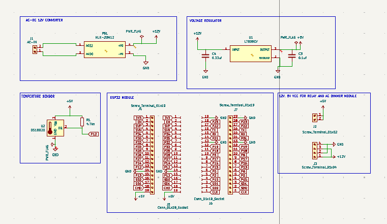
System Schematic
 Top layer of SmartBin control board
 Bottom layer showing power traces and isolation
Board Specifications:
| Component | Purpose | Interface |
|---|---|---|
| ESP32 | Main controller | - |
| HC-SR04 | Waste level detection | GPIO |
| TRIAC + Optocoupler | AC motor speed control | PWM |
| Solid State Relay | Heating element control | GPIO |
| 12V/5V Regulators | DC power supply | - |
| Current Sensor | Motor load monitoring | ADC |
220V AC ─┬─► AC Motor (via TRIAC dimmer)
         ├─► 50W Heater (via SSR)
         └─► AC-DC Converter ──► 12V ──► 5V ──► 3.3V ESP32
                                      ├─► Fan
└─► Sensors| Test | Method | Result |
|---|---|---|
| Motor speed control | Oscilloscope (PWM waveform) | ±5% accuracy |
| Temperature regulation | Thermocouple logging | ±2°C |
| Level detection | Manual measurement vs sensor | ±2mm |
| Power consumption | AC power meter | 125W max |
| Cycle time | Full dry → grind cycle | 45-60 min |
| Challenge | Solution |
|---|---|
| AC motor EMI interfering with ESP32 | Added optoisolation, separate ground planes |
| Heating element overshoot | Implemented PID control instead of bang-bang |
| Moisture damage to electronics | Enclosed PCB in sealed compartment |
| Inrush current on motor start | Added soft-start PWM ramp |
Fatai Oyetunji
Computer Science, University of Lagos
GitHub | LinkedIn
⭐ If you found this project useful, consider giving it a star!
| Qty | Value | Footprint | References |
|---|---|---|---|
| 2 | Conn_01x19_Socket | Connector_PinSocket_2.54mm:PinSocket_1x19_P2.54mm_Vertical | J5, J6 |
| 2 | Screw_Terminal_01x19 | TerminalBlock:TerminalBlock_MaiXu_MX126-5.0-19P_1x19_P5.00mm | J4, J7 |
| 1 | 0.1uf | Capacitor_SMD:C_0402_1005Metric_Pad0.74x0.62mm_HandSolder | C3 |
| 1 | 0.33uf | Capacitor_SMD:C_0402_1005Metric_Pad0.74x0.62mm_HandSolder | C4 |
| 1 | 4.7kn | Resistor_SMD:R_0402_1005Metric_Pad0.72x0.64mm_HandSolder | R1 |
| 1 | AC-IN | TerminalBlock:TerminalBlock_MaiXu_MX126-5.0-02P_1x02_P5.00mm | J1 |
| 1 | DS18B20 | Package_TO_SOT_THT:TO-92_Inline | U2 |
| 1 | HLK-20M12 | HLK-20M12:CONV_HLK-20M12 | PS1 |
| 1 | L7805CV | L7805CV:TO255P1040X460X1968-3 | U1 |
| 1 | Screw_Terminal_01x02 | TerminalBlock:TerminalBlock_MaiXu_MX126-5.0-02P_1x02_P5.00mm | J2 |
| 1 | Screw_Terminal_01x04 | TerminalBlock:TerminalBlock_MaiXu_MX126-5.0-04P_1x04_P5.00mm | J3 |
13 parts, built around the HLK-20M12, DS18B20 and L7805CV. The full list of its parts is on this page, with links to each part's symbol and footprint where PCBKit's library has them.
From the ola-oye/SmartBin repository on GitHub, at the commit this page was made from: the board is smartBin/smartBin.kicad_pcb and its schematic smartBin/smartBin.kicad_sch. PCBKit opens the board in the browser, with nothing to install.
Its repository states no licence, so its author keeps all rights: ask ola-oye before reusing the design.
SshgurkiratSingh/CCMS_PORTAL
A full-stack smart streetlight fleet management system with real-time monitoring, remote control, and analytics.

oamodular/uncertainty
This readme needs to be updated to reflect this and to talk about the many other languages that people have used to create new firmware for Uncertainty.


arcoslab/open-coroco-legacy
COmpliant RObot COntroller is a free software project aiming to create an impedance controller based on a stm32 microcontroller using bldc motors and strain gauges.

formulaslug/fs-3-schematics
Electrical Design Repository for fs-3 schematics and PCBs

andreasimonetto/lopielle
MIDI synth based on Yamaha OPLL FM synthesis sound chip (YM2413)

anorimaki/selfbalancing-robot
A buck converter to generate the 5V power rail would have been a better choice because it would be more efficient (extending battery life) and eliminate the need of a second battery (the circuit could be plugged with…