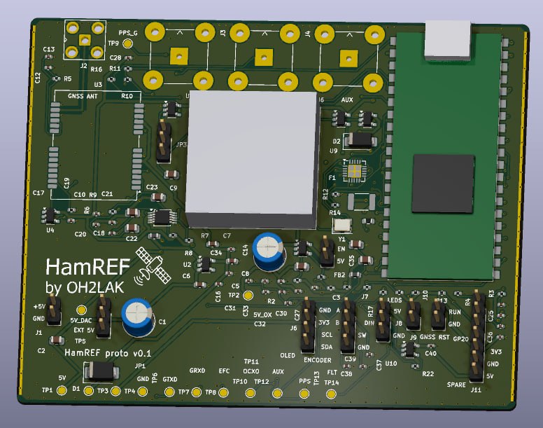
Hamref proto v0 1 is an open-source printed circuit board by OH2LAK, from the OH2LAK/HamRef repository on GitHub. It is a 4-layer board of 100 × 80 mm with 109 parts on 60 nets, routed with 952 tracks and 326 vias.
It is built around the 74AHCT1G125SE, 74LVC1G17Z and 74LVC1G125, with the LEA-M8S-0, AD5693RBRM and SI5351C-B-GM among its other parts. Its parts include 40 capacitors, 22 resistors, 11 connectors, 10 ICs and 2 diodes. It belongs with the radio and wireless boards and the RP2350 boards of this library.
A small GNSS-disciplined 10 MHz frequency reference and precision time server for the amateur radio shack — built around the u-blox LEA-M8S GNSS module.
Status: early architecture / pre-prototype. Proto-1 schematic and PCB (v0.1) are generated and routed, not yet built or tested; a firmware proof of concept (PIO counter + disciplining loop, host-simulated, not yet run on hardware) is in firmware/. This README documents the design as currently planned so the repo has a real starting point; sections below are marked TODO where work hasn't started.
Proto-1 bring-up board (v0.1): 4-layer, 100 × 80 mm (fits the Fischer AKG 105.26 case grooves), 3D view from KiCad. Design files in hardware/proto-v0.1/.
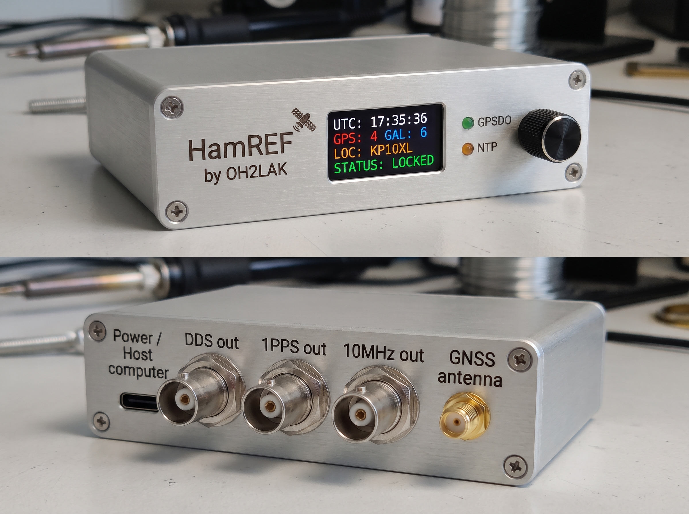
The proto-1 board has four coaxial connectors along the rear edge: SMA (GNSS antenna input), BNC REF OUT (10 MHz from the OCXO), BNC 1PPS OUT and BNC AUX OUT. AUX OUT outputs a programmable frequency (3.3 V CMOS) generated by the Si5351C synthesizer, which is clocked from the OCXO, so it is locked to the same reference as the 10 MHz output.
What this is
HamREF provides two things a well-equipped station needs and usually has to buy separately:
A 10 MHz reference output (BNC, 50 Ω) to lock transceivers, synthesizers, and test equipment, plus a programmable AUX output for other frequencies (e.g. 25 MHz, 27 MHz for satellite LNBs, 40 MHz for a Pluto SDR, or an arbitrary frequency).
A 1 PPS timing output which can be used to lock and synck devices to the world-standard one pulse per second.
A precision time source for the shack computer, disciplined by GNSS, accurate enough for FT8 and other digital modes.
Status (GNSS lock, satellite count, PPS accuracy, OCXO discipline state) is shown on a small monochrome OLED plus two multicolor status LEDs (GPSDO / NTP) on the front panel — color and blink/steady pattern indicate different states. A front-panel rotary encoder drives the menu; full parameter configuration is also available over USB (see Enclosure below).
Why not just use the GNSS module's own 10 MHz output?
The LEA-M8S can output a configurable timepulse from 0.25 Hz to 10 MHz directly, but that signal is a digitally synthesized pulse train (derived from the module's internal TCXO + fractional-N synthesizer), not a clean analog oscillator. At 10 MHz its jitter (the module's spec is 30 ns RMS / 60 ns 99% at 1 Hz) is significant relative to the 100 ns period, it can show small phase steps at each second boundary, and it provides no holdover if GNSS lock is lost.
HamREF instead uses the classic GPSDO approach: the LEA-M8S's single TIMEPULSE output is configured as 1PPS, and that one pulse-per-second reference is used by the MCU to discipline a separate free-running OCXO via a DAC-driven EFC loop with a long time constant. The 10 MHz output comes from the OCXO itself — far lower phase noise, plus holdover if satellite lock drops. The same 1PPS/NMEA data feeds the time service to the host computer.
Fischer Elektronik AKG 105.26 (part AKG1052680ME) — an extruded aluminum mini case for 100 mm eurocards, 105 × 100.3 × 26 mm, natural anodized, with integrated cooling-fin channels. Front and rear panels are separate 2 mm cover plates.
The 26 mm case height (≈22 mm usable panel height) ruled out the originally planned 240x240 color TFT. An EC11-class rotary encoder does fit, though (body ≈11.7×12–13×4.5–8.5 mm, ø7 mm panel bushing — verified against the Farnell EC11 datasheet), so the front panel keeps a physical control after all:
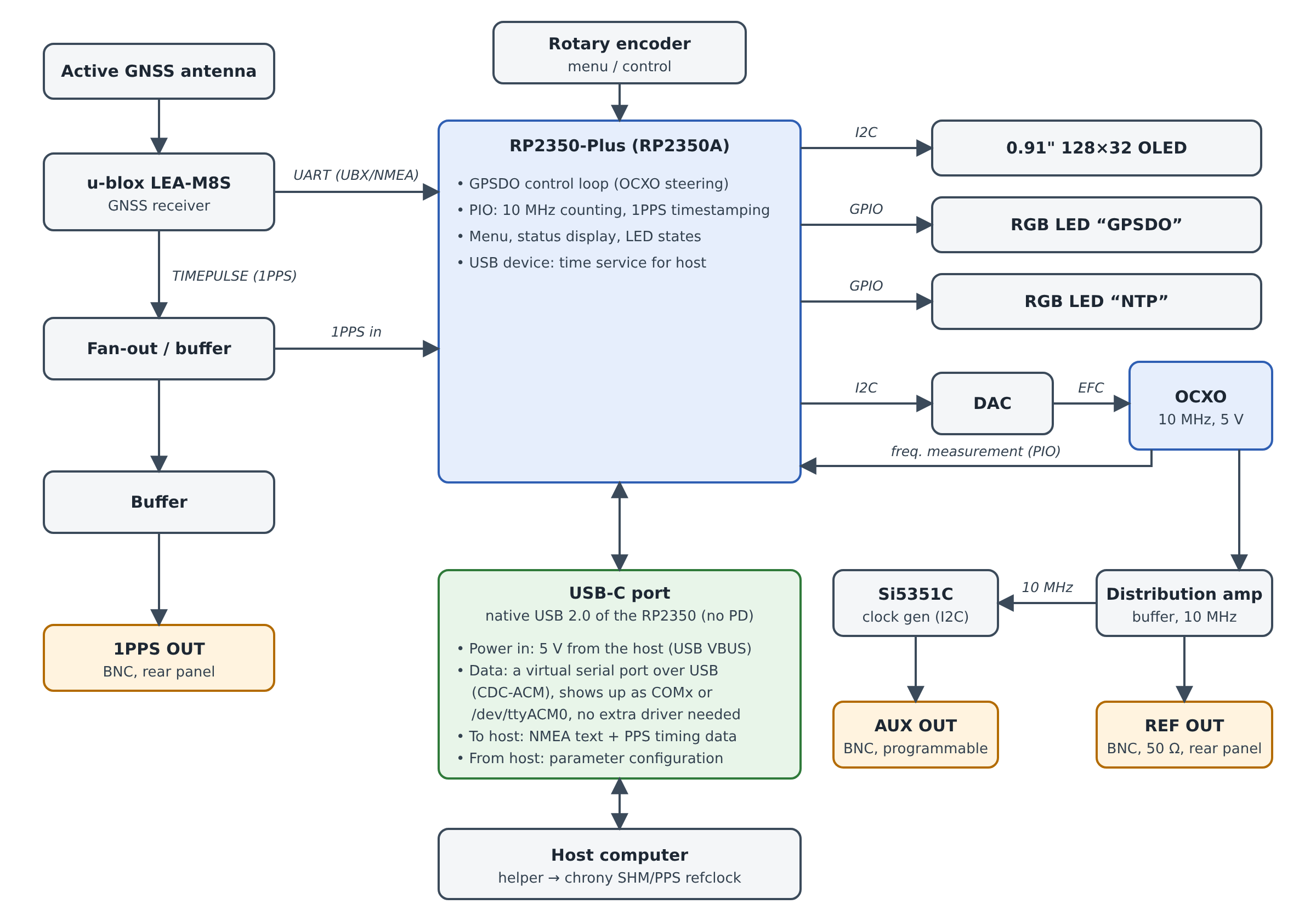
The GNSS module's 1PPS (TIMEPULSE) disciplines the OCXO through the MCU: the RP2350 measures the 10 MHz against the PPS with PIO and steers the EFC through the DAC. REF OUT (10 MHz) comes from the OCXO itself, 1PPS OUT from the GNSS TIMEPULSE, and AUX OUT is a programmable output (Si5351C clocked from the OCXO).
What is the USB-C port, in plain words? It is a normal USB-C connector (USB 2.0 only, no Power Delivery, so always 5 V) wired straight to the RP2350's own USB controller. One cable does two jobs: it powers the whole device and it carries data. The data side is a virtual serial port over USB (class CDC-ACM): the computer sees an ordinary serial port (COMx on Windows, /dev/ttyACM0 on Linux, /dev/cu.usbmodem… on macOS) and needs no special driver. Over that port the device sends the GNSS text sentences and PPS timing data to a small helper program on the computer, which feeds chrony; the computer can also send configuration commands back.
Acronym
Meaning
GNSS
Global Navigation Satellite System: GPS, Galileo, GLONASS, BeiDou
1PPS / PPS
One Pulse Per Second: a pulse aligned to the start of each UTC second
TIMEPULSE
u-blox name for the LEA-M8S's programmable timing-pulse output (here set to 1PPS)
UART
Universal Asynchronous Receiver/Transmitter: the simple serial link between LEA-M8S and RP2350
NMEA
Text sentences ($GPGGA, $GPRMC …) in which GNSS receivers report time, position and satellites
UBX
u-blox's own binary protocol, used to configure the LEA-M8S
USB VBUS
The 5 V power line of a USB cable
CDC-ACM
USB Communications Device Class, Abstract Control Model: the standard way to make a USB device look like a serial port
PD
USB Power Delivery: negotiation of voltages above 5 V (not used here)
I2C
Two-wire bus used for the OLED, the DAC and the Si5351C
GPIO
General-purpose input/output pin (drives the status LEDs, reads the encoder)
PIO
Programmable I/O: the RP2350's small hardware state machines that count the 10 MHz and timestamp the PPS without CPU jitter
Si5351C
Silicon Labs programmable clock generator (I2C); makes the AUX OUT frequency from the OCXO reference
OCXO
Oven-Controlled Crystal Oscillator: a crystal kept at constant temperature, the source of the 10 MHz
EFC
Electronic Frequency Control: the analog voltage input that fine-tunes the OCXO's frequency
DAC
Digital-to-Analog Converter: turns the MCU's number into the EFC voltage
SHM
Shared Memory: one of chrony's reference-clock interfaces, where the host helper hands over the timestamps
chrony
The time-sync daemon on Linux/macOS that disciplines the computer's clock (an NTP implementation)
NTP
Network Time Protocol
Key hardware decisions so far:
Item
Decision
Notes
GNSS module
u-blox LEA-M8S
Fixed — parts already on hand. Footprint and pinout are shared with LEA-M8T.
Antenna
Active, external
Antenna supervisor + R_BIAS per u-blox HIM.
MCU
RP2350A on a ready-made Raspberry Pi Pico 2 board
Ready-made board keeps HamREF easy to build as a kit. PIO blocks give deterministic 10 MHz counting and 1PPS timestamping without WiFi interrupt jitter; native USB (TinyUSB); UF2 firmware updates. No WiFi in v1. Raspberry Pi Pico 2 (micro-USB) remains a fallback.
Oscillator
5 V OCXO, analog EFC (CTI OSC5A2B02 selected for the prototype)
e.g. Trimble 65256 / IsoTemp 143-141 / CTI OC5SVC25 / Bliley NV47M1008 class part — physical height inside the 22 mm case is still open, see architecture doc.
Enclosure
Fischer Elektronik AKG 105.26 (AKG1052680ME)
105 × 100.3 × 26 mm extruded aluminum, 100 mm eurocard.
Display
0.91" 128x32 mono OLED, I2C
SSD1306-class, 38 × 12 mm PCB (active area 22.4 × 5.6 mm) — fits the 22 mm panel height with margin; 0.96" 128x64 modules do not.
EC11-class encoder confirmed to fit the 22 mm panel height. LED color/blink pattern encodes state (firmware TBD).
Rear panel
SMA (GNSS antenna), BNC (1PPS OUT), BNC (REF OUT 10 MHz), BNC (AUX OUT, programmable), USB-C (host + 5V power)
All connectors on the back; layout across the 105 mm width still to be confirmed at PCB stage.
Power + host link
USB-C
Powers the device (5V); CDC-ACM carries PPS/NMEA to a host-side helper feeding chrony (SHM/PPS refclock), and doubles as the configuration interface alongside the encoder/OLED menu.
See the architecture doc for the full reasoning, open questions, and the phased project plan.
Status / roadmap
Requirements and architecture defined
Enclosure selected (Fischer AKG 105.26) and display/panel layout locked to it
MCU selected (RP2350 / Pico 2)
Proto-PCB v0.1 (bring-up board, see architecture doc)
Breadboard proof of concept (PIO PPS capture + frequency counting, disciplining loop, USB time delivery)
KiCad schematic
PCB layout
Enclosure machining (panel cutouts)
Firmware proof of concept (PIO gate counter, disciplining loop, host simulation) - see firmware/
Firmware on real hardware (calibration, OLED/menu, GNSS configuration, host helper)
Calibration and verification against a reference
Repository structure
text
hardware/proto-v0.1/   KiCad project (schematic, PCB) for the proto-1 board
hardware/tools/        Python scripts that generate the schematic/PCB
firmware/              RP2350 firmware (Pico SDK) and host simulation
docs/                  Architecture notes, hardware plans, images
Building it yourself
Firmware: see firmware/README.md (Pico SDK, CMake, UF2). The disciplining loop can be tried without hardware with the host simulation described there. Hardware: open hardware/proto-v0.1/ in KiCad; the pre-order checklist is in docs/hardware/board-finishing-checklist.md. A bill of materials and bring-up guide will follow once the board is built.
It measures 100 × 80 mm and has 4 copper layers, 1.6 mm thick.
What parts does the Hamref proto v0 1 use?
109 parts, built around the 74AHCT1G125SE, 74LVC1G17Z, 74LVC1G125 and LEA-M8S-0. The full list of its parts is on this page, with links to each part's symbol and footprint where PCBKit's library has them.
Where can I download the Hamref proto v0 1 KiCad files?
From the OH2LAK/HamRef repository on GitHub, at the commit this page was made from: the board is hardware/proto-v0.1/hamref_proto_v0_1.kicad_pcb and its schematic hardware/proto-v0.1/clock.kicad_sch. PCBKit opens the board in the browser, with nothing to install.
Can I use the Hamref proto v0 1 design in my own project?
Its repository states no licence, so its author keeps all rights: ask OH2LAK before reusing the design.
MeshSat field kit hardware: the V1 kits as built, the V2 carrier PCB set for the Peli 1450 and the compact pocket-sized node (KiCad and OpenSCAD sources, generators, release files, build guides).
A central brain running on teensy or a lighter MCU to process any control signals (MIDI, CV, our own) into the same but adding logic, ADSRs, DCOs, CV matrices etc. to it