2 layers233.4 × 280 mm

 alexiosc/cft6
The CFT homebrew minicomputer
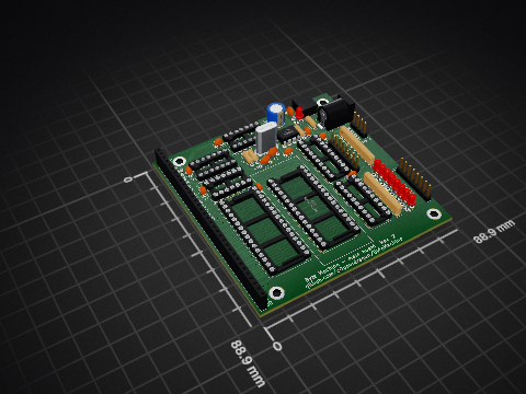
Cft board0 is an open-source printed circuit board by alexiosc, from the alexiosc/cft repository on GitHub, published under the GPL-3.0 licence. It is a 2-layer board of 233.4 × 280 mm with 299 parts on 472 nets, routed with 6,463 tracks and 1,866 vias.
It is built around the 74HC541D, 74HCT541D and 74LVC1G125, with the 74AC541SC, 74ACT245M and 74LVC1G17Z among its other parts. Its parts include 110 capacitors, 85 ICs, 53 resistors, 11 diodes and 3 connectors.


The CFT is a home-designed, home-built mini-computer made from scratch.
I've designed and built the instruction set, data path, processor, computer, software stack, cross-assembler, emulator, software toolchain and even some of the tools needed to do all this. You can call this a ‘fantasy mini’.
This project has been going since approximately 2001, in my Copious Free Time.
There isn't one, so I couldn't tell you what it's like. This project has been online since 2005 and it's been noticed by four or five people. Not quite enough for statistics.
This is a personal project, and the repository is made public as a curiosity. Expect everything to be wrong, broken, or dangerous.
Because it's fun.
To see how it's done.
To recall Those Heady Times.
To prove to myself I can do this.
The CFT is a long-term project built in my Copious Free Time. (a term used, as always, sarcastically, hence the name) It's a homebrew, self-designed, self-built Sixties-style 16-bit mini computer built out of 74-family integrated circuits. Check out the ChangeLog for the current status.
There may possibly be more stuff to look at, at https://www.bedroomlan.org/cft.
The project consists of:
I originally sat down with Eagle CAD and went crazy with it. I had 50 sheets of schematics for boards, all with a three-letter designator:
The currently planned peripherals are much more modest in scope, but they also morphed quite a bit. The processor can now do 24-bit addressing natively, the current microcode uses all of the available ROM space and a bunch of cards have joined forces. The current state of affairs looks like this:
I've built the MEM and DFP boards to pre-2019 specs and the computer was working on them.
The 2019 redesign goes for proper PCBs for everything, so things are taking a little extra time.
I was really proud of the front panel before the 2019 redesign, it worked great and showed the computer's entire status. There's support for up to 160 lights, 31 switches and two keylocks for that PDP-8 feel.
The downside was the wiring: there were no fewer than five 50-wire ribbon cables going to this crazy bastard.
The 2019 redesign keeps the layout, but can no longer display as much of the computer's status on the front panel. I'm working on it. On the upside, it now serialises data transmission and only a single 40-pin cable is needed.
To cut costs, the original front panel was made out of eight modules, each with up to 20 LEDs. The new front panel is made out of four modules, each with up to 40 LEDs. Each module daisy-chains to the next.
Switches are mounted on a separate plate and wired to a break-out board, or the closest front panel modules on the 2019 version.
Two words: wood paneling. Well, and a black acrylic front piece. The rest will depend on how big the card cage gets, but I'll scratch make the case out of sheet aluminium and wood.
There's just too much of it. The documentation was initially in LaTeX and got up to 500 pages before I gave that up and started converting it to HTML.
The 2019 redesign will need a redo of most of this, sadly, but the current documents for hardware that's currently around are available at https://www.bedroomlan.org/hardware/cft/book/.
I had to make my own tools for some of this, and wanted to make my own for some other parts.
Hardware tools include Flashprog, a zero-parts flash programmer with a modern serial interface. The interface formed the basis of the DEB and DFP cards' remote debugging interface and I'm quite happy with it.
Software tools include:
| Qty | Value | Footprint | References |
|---|---|---|---|
| 85 | 100nF | alexios:C_SMD_0805_2012Metric_Pad1.15x1.40mm_HandSolder | C1001, C1003, C1004, C1005, C1006, C1014, C1101, C1102, C1104, C1105, C1201, C1202, C1301, C1302, C1303, C1401 +69 |
| 31 | 4.7kΩ | alexios:R_SMD_0805_2012Metric_Pad1.15x1.40mm_HandSolder | R1001, R1002, R1004, R1005, R1014, R1016, R1101, R1102, R1201, R1401, R1501, R1601, R1602, R1604, R1605, R1606 +15 |
| 18 | 74HC541 | alexios:DIP-20_W7.62mm_Socket | U403, U407, U409, U410, U605, U608, U1102, U1105, U1201, U1202, U1301, U1303, U1801, U1802, U1803, U1804 +2 |
| 10 | 74HC574 | alexios:DIP-20_W7.62mm_Socket | U402, U406, U408, U604, U1101, U1104, U1302, U1705, U1706, U1707 |
| 9 | 100Ω | alexios:R_SMD_0805_2012Metric_Pad1.15x1.40mm_HandSolder | R921, R923, R1007, R1008, R1009, R1010, R1011, R1012, R1405 |
| 9 | 120pF | alexios:C_SMD_0805_2012Metric_Pad1.15x1.40mm_HandSolder | C921, C923, C1007, C1008, C1009, C1010, C1011, C1012, C1405 |
| 9 | 47µF | Capacitor_THT:CP_Radial_D6.3mm_P2.50mm | C1, C2, C3, C4, C5, C6, C7, C8, C9 |
| 8 | 74HC193 | alexios:DIP-16_W7.62mm_Socket | U201, U203, U206, U208, U301, U303, U306, U308 |
| 8 | 74HCT541 | alexios:DIP-20_W7.62mm_Socket | U202, U204, U205, U207, U302, U304, U305, U307 |
| 7 | 16V8 | alexios:DIP-20_W7.62mm_Socket | U601, U602, U901, U1401, U1610, U1611, U1901 |
| 6 | 680Ω | alexios:R_SMD_0805_2012Metric_Pad1.15x1.40mm_HandSolder | R602, R901, R902, R904, R1402, R1404 |
| 6 | LED_ALT | alexios:LED_0805_2012Metric_Pad1.15x1.40mm_HandSolder | D601, D901, D902, D903, D1402, D1404 |
| 5 | 74HC74 | alexios:DIP-14_W7.62mm_Socket | U606, U902, U904, U1402, U1603 |
| 5 | CUS520 | alexios:SOD-323 | D1001, D1004, D1501, D1502, D1503 |
| 4 | 10kΩ | Resistor_THT:R_Array_SIP9 | RN601, RN1301, RN1601, RN1602 |
| 4 | 30Ω | alexios:R_SMD_0805_2012Metric_Pad1.15x1.40mm_HandSolder | R1003, R1015, R1017, R1019 |
| 3 | 10kΩ | Resistor_THT:R_Array_SIP6 | RN1603, RN1701, RN1702 |
| 3 | 10µF | alexios:C_SMD_0805_2012Metric_Pad1.15x1.40mm_HandSolder | C1711, C1712, C1713 |
| 3 | 74LVC1G125 | alexios:SOT-23-5_HandSoldering | U906, U907, U1006 |
| 3 | AT27C020 | alexios:PLCC32 | U1701, U1702, U1703 |
| 2 | 10kΩ | alexios:R_SMD_0805_2012Metric_Pad1.15x1.40mm_HandSolder | R601, R1603 |
| 2 | 1kΩ | alexios:Potentiometer_Bourns_67W | RV901, RV902 |
| 2 | 22pF | alexios:C_SMD_0805_2012Metric_Pad1.15x1.40mm_HandSolder | C920, C922 |
| 2 | 74AC541 | alexios:DIP-20_W7.62mm_Socket | U501, U503 |
| 2 | 74AC74 | alexios:DIP-14_W7.62mm_Socket | U1403, U1404 |
| 2 | 74ACT245 | alexios:DIP-20_W7.62mm_Socket | U909, U910 |
| 2 | 74HC139 | alexios:DIP-16_W7.62mm_Socket | U1003, U1506 |
| 2 | 74HC251 | alexios:DIP-16_W7.62mm_Socket | U1501, U1505 |
| 2 | SolderJumper_3_Bridged23 | alexios:SolderJumper-3_P1.3mm_Bridged23_RoundedPad1.0x1.5mm | JP1601, JP1603 |
| 1 | 0Ω | alexios:R_SMD_0805_2012Metric_Pad1.15x1.40mm_HandSolder | R1018 |
| 1 | 10kΩ | Resistor_THT:R_Array_SIP5 | RN1201 |
| 1 | 1μF | alexios:C_SMD_0805_2012Metric_Pad1.15x1.40mm_HandSolder | C1016 |
| 1 | 47µF | alexios:C_SMD_0805_2012Metric_Pad1.15x1.40mm_HandSolder | C1002 |
| 1 | 6116SA15TPG | alexios:DIP-24_W7.62mm_Socket | U603 |
| 1 | 74AC08 | alexios:DIP-14_W7.62mm_Socket | U1502 |
| 1 | 74AC157 | alexios:DIP-16_W7.62mm_Socket | U1005 |
| 1 | 74AC161 | alexios:DIP-16_W7.62mm_Socket | U1902 |
| 1 | 74AC191 | alexios:DIP-16_W7.62mm_Socket | U1004 |
| 1 | 74AC257 | alexios:DIP-16_W7.62mm_Socket | U1704 |
| 1 | 74AC32 | alexios:DIP-14_W7.62mm_Socket | U1503 |
| 1 | 74HC138 | alexios:DIP-16_W7.62mm_Socket | U401 |
| 1 | 74HC14 | alexios:DIP-14_W7.62mm_Socket | U903 |
| 1 | 74HC590 | alexios:DIP-16_W7.62mm_Socket | U1001 |
| 1 | 74HC85 | alexios:DIP-16_W7.62mm_Socket | U1601 |
| 1 | 74HC86 | alexios:DIP-14_W7.62mm_Socket | U1504 |
| 1 | 74LVC1G17 | alexios:SOT-23-5_HandSoldering | U1002 |
| 1 | CFT-2021-Peripheral-Bus | alexios:DIN41612_B_3x32_Horizontal | P2 |
| 1 | CFT-2021-Processor-Bus | alexios:DIN41612_B_3x32_Horizontal | P1 |
| 1 | CXO_DIP8 | alexios:Oscillator_DIP-8-socket | X1 |
| 1 | C_SMD_0805_2012Metric_Pad1.15x1.40mm_HandSolder | alexios:C_SMD_0805_2012Metric_Pad1.15x1.40mm_HandSolder | SPARE |
| 1 | Conn_01x02 | Connector_PinHeader_2.54mm:PinHeader_1x02_P2.54mm_Horizontal | J1001 |
| 1 | DIP-20_W7.62mm_Socket | alexios:DIP-20_W7.62mm_Socket | SPARE |
| 1 | LOGO | alexios:CFT | G*** |
| 1 | SolderJumper_3_Bridged12 | alexios:SolderJumper-3_P1.3mm_Bridged12_RoundedPad1.0x1.5mm | JP1602 |
| 1 | tactile_switch | Button_Switch_THT:SW_Tactile_SPST_Angled_PTS645Vx39-2LFS | SW1001 |
The 280 most common of 299 parts.


Cptscorcher/Excallibur-64
A reimagining of the seminal Excalibur 64 Computer

dbuchwald/Z80DevBoard
Simple Z80 based prototyping and development board designed as extension to Arduino Mega 2560


c0pperdragon/BreadBin
A CPU made of 7400 logic on breadboards - inside a bread bin ;-)


fran150/clementina-hardware
KiCad schematic for Clementina, a 3.3V W65C02S computer with a Raspberry Pi Pico 2 W (MIA) handling video, audio, storage and I/O.
It measures 233.4 × 280 mm and has 2 copper layers, 1.6 mm thick.
299 parts, built around the 74HC541D, 74HCT541D, 74LVC1G125 and 74AC541SC. The full list of its parts is on this page, with links to each part's symbol and footprint where PCBKit's library has them.
From the alexiosc/cft repository on GitHub, at the commit this page was made from: the board is kicad/cft/cft-board0/cft-board0.kicad_pcb. PCBKit opens the board in the browser, with nothing to install.
Its repository publishes it under the GPL-3.0 licence: you may reuse it on that licence's terms (keep the author's notice, and for a copyleft licence share your changes alike).