
4 layers93.7 × 43.7 mm
Flight Computer
SunDevilRocketry/Flight-Computer
General purpose flight computer for high powered rocketry projects.
113 parts5
 Nv7-GitHub/simmevator
An elevator tracker and floor display for Simmons Hall, MIT
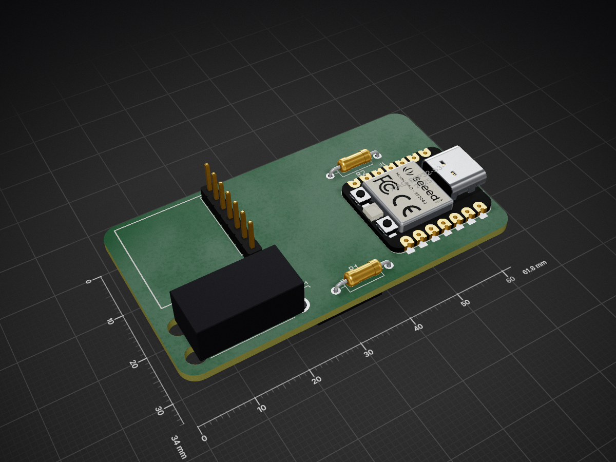
Simmevator pcb is an open-source printed circuit board by Nv7-GitHub, from the Nv7-GitHub/simmevator repository on GitHub. It is a 2-layer board of 61.8 × 34 mm with 6 parts on 26 nets, routed with 57 tracks and 0 vias.
It is built around the BMP390. Its parts include 3 connectors, 2 resistors and 1 IC. It belongs with the lEDs and displays boards and the ESP32 boards of this library.
An elevator tracker and floor display for Simmons Hall, MIT.
A barometer rides in each elevator car and works out which floor the car is on. It broadcasts that over LoRa to a bridge in its own shaft, which relays it over ESP-NOW to a screen on every landing of that shaft. Each screen shows the floor in numbers you can read from down the corridor, an up/down arrow while the car is moving, the transmitter's battery voltage, and how far that elevator has travelled in the last day.
Three shafts are covered: A, B and C. A and C serve a basement as well as floors 1-10, so they have eleven landings each; B has ten. That is 3 transmitters, 3 bridges and 32 displays.
| elevator A | elevator B | elevator C | |
|---|---|---|---|
| landings | B, 1-10 | 1-10 | B, 1-10 |
| displays | 11 | 10 | 11 |
| LoRa frequency | 913.0 MHz | 915.0 MHz | 917.0 MHz |
| ESP-NOW channel | 6 | 1 | 11 |
txId | 'A' | 'B' | 'C' |
The three systems are independent end to end. A car is heard only by its own bridge, a screen only ever sees its own shaft's car, and no packet crosses from one shaft to another.
Each car node runs on a battery, unattended, for about seven weeks.
A floor is about 2.9 m of altitude, and a BMP390 resolves that easily — noise in this shaft is 0.045 m, sixty times smaller. The difficulty is that the reference pressure moves. Over a 3 h capture in this building the sea-level reference wandered 9.9 m of apparent altitude, more than three floor heights. Any fixed pressure-to-floor table slides through several floors in an evening.
So absolute altitude cannot decide the floor. Two facts rescue it:
round(jump / pitch) is a strong error-correcting code.The algorithm therefore reads floor changes from jumps between stops and treats absolute position as a slowly-tracked side quantity. It learns the building as it goes — the floor spacing, each landing's height, how many floors exist — with nothing configured in advance. On the reference capture it converges in five minutes to a pitch of 2.871 m and ten floors, and stays within ±1%.
The algorithm is not this repo's invention. It was developed and measured against
real data in the elevatormons bring-up repo, and is fully
documented in elevatormons/docs/ALGORITHM.md — including the four approaches
that were tried and failed, which are more instructive than the one that worked.
This repo ports it to C++ and builds a system around it.
The node holds the sensor, so it sees an unbroken 1 Hz stream and decides the floor locally. It broadcasts the answer, not the raw pressure.
That one choice makes radio loss harmless. A dropped packet can only age what a screen shows; it can never corrupt the floor, because the next packet carries the current floor outright. There is no state to resync and no way for a bad link to produce a wrong number. If the bridge decided the floor instead, every dropout would become a correctness problem.
  ELEVATOR CAR (battery)          MID-SHAFT (wall)          EVERY LANDING (wall)
  ┌──────────────────────┐        ┌──────────────┐          ┌──────────────┐
  │ XIAO ESP32S3         │        │ XIAO ESP32S3 │  ESP-NOW │ CYD x10/x11  │
  │  BMP390 @ 4 Hz       │  LoRa  │ + Wio-SX1262 │ ───────► │ ILI9341      │
  │  FloorMonitor @ 1 Hz │ ─────► │              │  flood   │ relay + draw │
  │  model in NVS        │913/915/│ LoRa -> mesh │ ch 6/1/11│              │
  │  battery sense       │917 MHz │ origin node  │ ◄──────► │ peer relay   │
  │  Wio-SX1262          │        └──────────────┘          └──────────────┘
  └──────────────────────┘
One of these per shaft, three times over. The column of radio settings is the only difference between them.
The transmitter samples the barometer, runs the floor algorithm, and sends two
kinds of packet: an 8-byte STATE every 2 seconds while the car is moving, and a
24-byte STATS every 60 seconds carrying battery voltage, distance travelled, and
the learned building model.
The bridge does nothing but listen on LoRa and re-emit over ESP-NOW. It holds no state worth losing.
The displays flood packets to each other so the signal reaches floors the bridge cannot: every screen rebroadcasts each new sequence number exactly once, up to eight hops. Flooding rather than a fixed 5→6→7 chain means one unplugged screen does not cut off everything above it.
Separate LoRa frequencies, because three cars on one frequency is pure ALOHA.
There is no carrier sense: a transmitter that is about to send has no idea another
shaft's car is mid-packet. A STATE packet is 297 ms and goes out every 2 s while
the car is active. STATE is not gated on motion alone - it keeps running for 10 s
past every stop - so the duty fraction is the 0.90 STATE-active figure, and each
car offers 0.5 x 0.90 = 0.45 packets per second. ALOHA's vulnerable window is
two packet lengths, 2 x 0.297 = 0.594 s, so a given packet survives two
interferers with probability exp(-2 x 0.45 x 0.594) = 0.586 - about two STATE
packets in five lost, on top of the 5.21% the shaft already costs
(ALGORITHM.md §9), and concentrated in exactly the evening peak when all three
cars are busy at once. So A, B and C sit on 913.0, 915.0 and 917.0 MHz: 2 MHz of
separation against a 125 kHz occupied bandwidth, sized for a transmitter passing
close to another shaft's bridge rather than for the typical case. A per-elevator
sync word would not fix this and must not be mistaken for a fix - it is checked
after demodulation, so it classifies wreckage rather than preventing it.
docs/PROTOCOL.md carries the full arithmetic.
Separate ESP-NOW channels, because each mesh should stay the system that was
measured. No display ever needs another shaft's data, so the three floods run on
channels 6, 1 and 11 and each one remains the ten- or eleven-node, single-origin
flood that docs/MESH.md measured and tuned - so every number in it stays valid as
written. One building-wide flood instead would break
in two ways: the per-bridge origSeq counters would collide, because the dedup ring
tests sequence numbers for equality with no notion of who minted them, so bridge
A's frame 4113 would silently swallow bridge C's; and the 5-40 ms relay jitter
window would be swamped, since 32 displays and 3 bridges put roughly 96
transmissions of about 1.3 ms each into a 35 ms window, some 3.5x oversubscribed,
re-creating the exact collision the jitter exists to prevent. Channel isolation
makes both problems not exist rather than patching them; the only thing given up is
cross-shaft path diversity, which is worthless when the shafts are far apart.
docs/MESH.md works through both.
Airtime is the entire power budget. A LoRa packet at SF10 costs hundreds of milliseconds at about 118 mA, and the car in this building is moving 71% of an evening peak. Thirty days off a 10 Ah LiFePO4 pack means staying under 40 mA average. Send a 297 ms packet every 2 s around the clock and the radio alone is ~21 mA; stay awake between samples and the baseline is ~25 mA instead of ~3 mA. Together that is ~47 mA - the requirement is missed before anything else has gone wrong.
Two changes fix it without making the display feel slower:
That lands at roughly 23 mA average, about 50 days on a 10 Ah LiFePO4 pack, using the evening-peak traffic rate — a real week including nights does better.
That is arithmetic, not a measurement. No board has been on a meter yet, and the light-sleep floor is the number in it I would trust least: the ~3 mA is the datasheet figure, while the actual XIAO board also carries a power LED and a charge IC. The spec lists the four unmeasured draws and what to do about them.
elevatormons/platformio.ini configures the barometer link at BW62.5 kHz, but
ALGORITHM.md §9 records that the actual field run — the one that measured 5.21%
packet loss over three hours in this shaft — was at BW125 kHz and only 14 dBm.
This project uses BW125 at 22 dBm on all three shafts. The 915.0 MHz that the bring-up repo and the field run used is now elevator B's frequency specifically - A and C sit 2 MHz either side of it, and nothing else about the link differs between them. That is the configuration with real in-shaft evidence, running with 8 dB more margin than the run that produced the 5.21% figure, and it costs 297 ms per packet instead of 725 ms. The same section notes that loss barely tracks signal-to-noise (r = −0.13) — it is shadowing and interference, not a decode floor — so buying margin with a higher spreading factor would cost airtime linearly and buy very little.
┌────────────────────────────┬──────────────┐
│                            │      ▲       │
│      ██████     ██         │    UP        │
│      ██  ██     ██         │              │
│      ██  ██     ██         │  12.7 V      │
│      ██  ██     ██         │  ■■■■■□      │
│      ██████     ██         │              │
│                            │  2.1 mi      │
│                            │  today       │
└────────────────────────────┴──────────────┘
The floor number is drawn as vector segments rather than a font — anything large enough to read at distance looks soft as a bitmap. While the car is moving the number sweeps through the intermediate floors and the arrow lights up; on arrival it snaps to the floor the algorithm confirmed.
Battery voltage and the 24-hour distance come from the transmitter once a minute, so every screen in that shaft agrees. Between heartbeats each screen extrapolates the distance from floor changes it observes, so the number ticks in real time rather than jumping once a minute.
If a screen stops hearing the mesh it dims, then greys out and turns its onboard LED amber — a dead link is visible from the corridor rather than silently showing a floor from twenty minutes ago.
That is normal operation. There are three further states that appear only while a
shaft is being commissioned or is misconfigured, all derived from fields the wire
already carries: LEARNING, showing how many landings the car has spanned so far
over the word LEARNING and OF 11; ANCHORING, asking for a ride to both ends of the shaft
after the transmitter restored its model from NVS; and CHECK SHAFT, which means
the car is confidently reporting a floor count this shaft does not have. The last
one is the whole reason the others exist. An elevator A car commissioned over a
period in which nobody presses B learns a span of ten landings, is internally
consistent, sets its model ready, and would label every screen in the shaft one
floor too low indefinitely - and it is the display, holding the only copy of how
many landings the building has, that can catch it. That mismatch is CHECK SHAFT's
only cause, and because every display in a shaft carries the same label table and
hears the same bridge, it appears on all of them at once or on none. It does not
catch a mis-flashed display: the mesh channels are 6, 1 and 11, which do not
overlap, so a display flashed for the wrong shaft never hears its landing's bridge
at all and sits on the splash screen forever. docs/FLASHING.md has the
commissioning procedure. -- means "this screen has heard frames but has no
confirmed floor"; a screen that has heard nothing since boot still shows the
splash.
| Document | What is in it |
|---|---|
| Design spec | The whole system: power budget, protocols, verification gates, parts list |
| Three-elevator deployment | The per-shaft frequency and channel plan, the basement, the commissioning screens |
| docs/HARDWARE.md | Wiring, the battery divider, the buck regulator, antenna placement |
| docs/FLASHING.md | Which firmware goes on which board, and how |
| docs/PROTOCOL.md | Both wire formats, field by field |
| docs/MESH.md | How the ESP-NOW flood behaves and how to debug it |
| docs/ALGORITHM_PORT.md | How the C++ port maps to the Python reference, and the evidence it matches |
elevatormons/docs/ALGORITHM.md | The algorithm itself — the source of truth, not maintained here |
PlatformIO. Nine firmware environments - three roles across three elevators:
pio run -e elevator_tx_b   -t upload    # shaft B's car node
pio run -e bridge_rx_b     -t upload    # shaft B's bridge
pio run -e floor_display_b -t upload    # each of shaft B's screens
pio test -e native                      # host unit tests
Substitute _a or _c for the other two shafts. The suffix is the whole of an
image's identity: it carries the LoRa frequency, the ESP-NOW channel, the txId
and the floor label table, so a display built _b and hung in shaft A is deaf on
channel 1 while that landing's bridge floods channel 6, and never leaves its splash
screen. There is no runtime elevator selection to correct it with.
docs/FLASHING.md has the which-image-on-which-board table, the board labelling,
and the commissioning check that catches exactly that mistake.
The port is verified by replaying the real 3 h capture through the actual C++ implementation and diffing it against the Python reference sample by sample:
pio run -e sim && .pio/build/sim/program sim/cpp_broadcasts.csv
python3 sim/compare_to_python.py sim/cpp_broadcasts.csv
The gate that matters is the first line of the comparator's output: the C++ floor sequence has to be identical to the Python's over all 10,950 samples. Five numeric gates bound the rest - ten floors, 2.871 m pitch ±1 mm, 3409 m travelled ±0.1%, 357 floor-to-floor moves ±1, 255 confirmed stops ±1.
ALGORITHM.md §5 reports 356 moves and 256 stops, and that is not a
disagreement: §5 measured the raw capture, which is a radio log with 49 dropouts
in it, while the replay runs the gap-filled 1 Hz stream the node would actually
have been handed. The Python reference produces 357/255 on that input too.
docs/ALGORITHM_PORT.md §6 works through it.
| Qty | Value | Footprint | References |
|---|---|---|---|
| 1 | 100k | Resistor_THT:R_Axial_DIN0207_L6.3mm_D2.5mm_P10.16mm_Horizontal | R1 |
| 1 | 20k | Resistor_THT:R_Axial_DIN0207_L6.3mm_D2.5mm_P10.16mm_Horizontal | R2 |
| 1 | BMP390 | Connector_PinHeader_2.54mm:PinHeader_1x07_P2.54mm_Vertical | J3 |
| 1 | BUCKREG | custom:BUCKREG | J2 |
| 1 | PWR_IN | Connector_Wire:SolderWire-1.5sqmm_1x02_P6mm_D1.7mm_OD3mm_Relief | J1 |
| 1 | XIAO-ESP32-S3-SMD | Seeed_Studio_XIAO_Series:XIAO-ESP32-S3-DIP | U1 |
It measures 61.8 × 34 mm and has 2 copper layers, 1.6 mm thick.
6 parts, built around the BMP390. The full list of its parts is on this page, with links to each part's symbol and footprint where PCBKit's library has them.
From the Nv7-GitHub/simmevator repository on GitHub, at the commit this page was made from: the board is simmevator_pcb/simmevator_pcb.kicad_pcb and its schematic simmevator_pcb/simmevator_pcb.kicad_sch. PCBKit opens the board in the browser, with nothing to install.
Its repository states no licence, so its author keeps all rights: ask Nv7-GitHub before reusing the design.
SunDevilRocketry/Flight-Computer
General purpose flight computer for high powered rocketry projects.


BioMorphic-Intelligence-Lab/Whisker-3D-Localization
A Biomorphic Whisker Sensor for Aerial Tactile Applications , Chaoxiang Ye, Guido de Croon, and Salua Hamaza. 2024 IEEE International Conference on Robotics and Automation (ICRA 2024).

Ilikemining1/ESPWatchS3
ESP32-S3 based smartwatch with CrystalFontz 240x240 1.3in LCD.

katetriestocode/trailmap
this is the working version! (disclaimer: no antenna as it has not delivered yet, so manual gps coords insertion for now!)

WojtaCZ/telinksensor-hw
HW repository for TLSR8258 based temperature, humidity and pressure sensor

Afligh8/FlightController
A simple Plug and Play FLight Controller for Wings. Supports two motors with ESC, 6 PWM pins, SPI, I2C and Serials. Also 6 ports for servos and extra GPIO pins for debug and freelance.
