

4 layers34.8 × 35.6 mm
Sw63 mk4 v2
xx0x/sw63
Sci-fi inspired electronic watch. MK4 currently in the development (out in 2026).
70 parts2MIT
 nurk/kitchen_timer
Kitchen timer
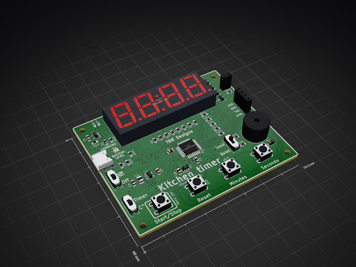
Kitchen timer 6.5 is an open-source printed circuit board by nurk, from the nurk/kitchen_timer repository on GitHub, published under the AGPL-3.0 licence. It is a 2-layer board of 79.5 × 66 mm with 57 parts on 66 nets, routed with 356 tracks and 146 vias.
It is built around the ATMEGA4808-AF, LM321 and TPS613222ADBV, with the DIO5518BST5, LTC-5723HR and MMBT2222A among its other parts. Its parts include 21 resistors, 7 switches, 6 capacitors, 5 ICs and 5 transistors. It belongs with the AVR (ATmega, ATtiny) boards of this library.


I am not a microcontroller developer nor am I a C-plusplus developer. I am also definitively not a hardware designer.
A long time ago my lovely sister gave me a kitchen timer which would beep once when there are 10 minutes left and twice when there are 5 minutes left. Unfortunately time got the better of the timer and it broke but I got hooked on those features.
I have been unable to find a replacement but after dabbling with some circuits a bit I thought I might be able to make my own.
This repository contains the version(s) that I deem worthy of the internet.
You will find a software and hardware folder with each containing the respective versions.
The hardware folder contains a KiCad project where the symbols and footprints used have been added to a local library. You will also find a pdf of the schematic, a screenshot of the pcb and a screenshot of the 3D rendering.
The software folder contains an arduino ide project with the, well, software.
I am not going to explain how to use a kitchen timer. If the main function of the 4 buttons does not speak for themselves I did really bad. I am only going to explain the extra features.
This switch toggles the display to show the timer and the measured temperature.
I bought cheap buzzers on amazon and they all seem a bit different. Some are quiet and some are loud. Because I was tired of changing the inline resistor for the buzzer I added a toggle to switch between two values. One is louder, the other is quieter.
Because you can fully turn off this device a way was needed to set the time for when you turn on the device. The chance of you needing a timer of 0 minutes and 0 seconds is very slim.
After setting a time you can long press the Reset button until you hear a second beep and the set time will be stored. When cycling the power the stored time will be loaded.
When you long press the Start/Stop button the letter A will appear and you will have entered the setup menu. After releasing the Start/Stop button you will see A5. 0. Clicking the Start/Stop button will cycle through the menu items:
| Displayed | Meaning |
|---|---|
A5. 0 | 5 minute alarm |
A10.0 | 10 minute alarm |
A15.0 | 15 minute alarm |
A20.0 | 20 minute alarm |
C 0.0 | Temperature offset* |
* This was added in version 6.4. It is a C because I cannot make a T with a 7-segment display.
For the alarms, the value after the . is the number of beeps that will sound when there are 'x' minutes left. You can use the Minutes button to increase the number of beeps and the Seconds button to decrease the number of beeps.
To exit the setup menu just click the Reset button.
Some component sizes might seem big for some. Especially resistors and capacitors of size 0805. Keep in mind I am hand soldering this and I am becoming an old fart with bad eyesight.
The microcontroller is an ATmega4808 which has way more flash storage than is needed. I still chose this one because it is what I have and I am not going to buy a new variant for each project I do.
The battery charge controller I chose only charges at 500mA. So you will need a battery with at least this capacity (or you have to change the resistor on the programming pin). I have a 2000mA battery connected and I takes a fair while to charge.
This is not a cost effective way to get a kitchen timer. If you need one you are better of going to the store and buying one.
| Qty | Value | Footprint | References |
|---|---|---|---|
| 8 | 220R | 00_local:R_0805_2012Metric_Pad1.20x1.40mm_HandSolder | R1, R2, R3, R4, R5, R6, R7, R8 |
| 6 | 1k | 00_local:R_0805_2012Metric_Pad1.20x1.40mm_HandSolder | R11, R12, R13, R15, R17, R20 |
| 5 | MMBT2222A | 00_local:SOT-23-3 | Q1, Q2, Q3, Q4, Q5 |
| 4 | MountingHole | 00_local:MountingHole_3.2mm_M3 | H1, H2, H3, H4 |
| 3 | 100n | 00_local:C_0805_2012Metric_Pad1.18x1.45mm_HandSolder | C1, C2, C6 |
| 2 | 22u | 00_local:C_0805_2012Metric_Pad1.18x1.45mm_HandSolder | C4, C5 |
| 2 | 5k1 1% | 00_local:R_0805_2012Metric_Pad1.20x1.40mm_HandSolder | R9, R10 |
| 1 | 10k 1% | 00_local:R_0805_2012Metric_Pad1.20x1.40mm_HandSolder | R21 |
| 1 | 10u | 00_local:C_0805_2012Metric_Pad1.18x1.45mm_HandSolder | C3 |
| 1 | 2k 1% | 00_local:R_0805_2012Metric_Pad1.20x1.40mm_HandSolder | R14 |
| 1 | 300R | 00_local:R_0805_2012Metric_Pad1.20x1.40mm_HandSolder | R16 |
| 1 | 47R | 00_local:R_0805_2012Metric_Pad1.20x1.40mm_HandSolder | R18 |
| 1 | 5R | 00_local:R_0805_2012Metric_Pad1.20x1.40mm_HandSolder | R19 |
| 1 | ATmega4808-A | 00_local:TQFP-32_7x7mm_P0.8mm | U2 |
| 1 | BREAKOUT | 00_local:PinSocket_1x04_P2.54mm_Vertical | J3 |
| 1 | Buzzer | 00_local:MagneticBuzzer_ProSignal_ABT-410-RC | BZ1 |
| 1 | CHRG_LED | 00_local:D_0805_2012Metric_Pad1.15x1.40mm_HandSolder | D1 |
| 1 | CVH252009-2R2M | 00_local:L_1008_2520Metric_Pad1.43x2.20mm_HandSolder | L1 |
| 1 | DIO5518B | 00_local:SOT-23-5 | U3 |
| 1 | FUNCTION_SELECTOR | 00_local:SW_Slide_SPDT_MINI | SW7 |
| 1 | JST PH 2.0 | 00_local:JST_PH_S2B-PH-K_1x02_P2.00mm_Horizontal | J1 |
| 1 | LM321 | 00_local:SOT-23-5 | U5 |
| 1 | LTC-5723HR | 00_local:CA56-12EWA | U1 |
| 1 | MBR0520 | 00_local:D_SOD-123 | D3 |
| 1 | MINUTES | 00_local:SW_PUSH_6mm | SW3 |
| 1 | NRBE104F3435B2F | 00_local:PinSocket_1x02_P2.54mm_Vertical | TH1 |
| 1 | ON/OFF | 00_local:SW_Slide_SPDT_MINI | SW1 |
| 1 | RESET_TIME | 00_local:SW_PUSH_6mm | SW4 |
| 1 | SECONDS | 00_local:SW_PUSH_6mm | SW2 |
| 1 | START/STOP | 00_local:SW_PUSH_6mm | SW6 |
| 1 | TPS613222ADBV | 00_local:SOT-23-5 | U4 |
| 1 | USB_C | 00_local:USB_C_Receptacle_GCT_USB4125-xx-x-0190_6P_TopMnt_Horizontal | J2 |
| 1 | VOLUME | 00_local:SW_Slide_SPDT_MINI | SW5 |
| 1 | WS2812B-2020 | 00_local:LED_WS2812B-2020_2.0x2.0mm | D2 |
It measures 79.5 × 66 mm and has 2 copper layers, 1.6 mm thick.
57 parts, built around the ATMEGA4808-AF, LM321, TPS613222ADBV and DIO5518BST5. The full list of its parts is on this page, with links to each part's symbol and footprint where PCBKit's library has them.
From the nurk/kitchen_timer repository on GitHub, at the commit this page was made from: the board is hardware/kitchen_timer_6.5/kitchen_timer_6.5.kicad_pcb and its schematic hardware/kitchen_timer_6.3/kitchen_timer_6.3.kicad_sch. PCBKit opens the board in the browser, with nothing to install.
Its repository publishes it under the AGPL-3.0 licence: you may reuse it on that licence's terms (keep the author's notice, and for a copyleft licence share your changes alike).
xx0x/sw63
Sci-fi inspired electronic watch. MK4 currently in the development (out in 2026).

filliformes/pandore
pandore is an open-source digital audio instrument protyping platform based on the LattePanda Mu.

fredriknk/msense
Open Source hardware kicad source files for a NRF9160 based methane sensor utilizing MOX sensor.

fredriknk/ssense-lte
This is the kicad template i use for my projects. The latest addition is a buildoutputs.py automating picture generation, 3d models and sch/prints, Gerbers ETC! Pretty sweet!


